Drilling device for brake drum

A technology of drilling device and brake drum, applied in positioning device, feeding device, boring/drilling and other directions, can solve the problems of reducing the drilling efficiency of brake drum, cumbersome operation and complex overall structure, etc. The overall structure is simple and the effect of improving work efficiency

Inactive Publication Date: 2016-01-20
重庆市璧山区振昌汽车配件有限公司
View PDF6 Cites 3 Cited by
  • Summary
  • Abstract
  • Description
  • Claims
  • Application Information

AI Technical Summary

Benefits of technology

In this system, there are three main components - one for driving the movement of the driven rods in response to signals from an electronic control unit (ECU). Another component helps hold the brackets securely during machining operations. These technical features improve the accuracy and effectiveness of machine tools used on vehicles' wheels or axles.

Problems solved by technology

This patented technical problem addressed in this patents relates to improving the performance and functionality of machinery equipment components during drilling operations while reducing their wear or damage caused by excessive vibrations from high-speed cutting motors.

Method used


Image

  • Drilling device for brake drum

Examples


Embodiment Construction

[0013] The present invention will be described in further detail below by means of specific embodiments:

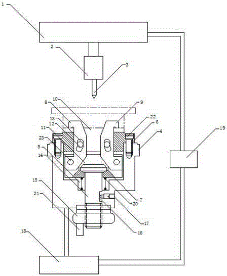
[0014] The reference signs in the drawings of the description include: press 1, motor 2, drill bit 3, base 4, step space 5, upper template 6, lower template 7, left jaw 8, right jaw 9, upper groove 10 , lower groove 11, positioning protrusion 12, guide hole 13, drive rod 14, turntable 15, chute 16, stop screw 17, sheave mechanism 18, controller 19, compression spring 20, handle 21, bolt 22, Pin shaft 23.

[0015] The embodiment is basically as attached figure 1 Shown: the drilling device of the brake drum, including the upper power device, the clamping device and the lower power device, the upper power device includes a press machine 1, a motor 2 fixedly connected to the left side of the press machine 1, and a motor 2 fixedly connected to the left side of the motor 2 Drill bit 3; the clamping device includes a base 4, a clamping mechanism and a driving mechanism, and a ste


PUM


Abstract

The invention discloses a drilling device for a brake drum. The drilling device comprises an upper power unit, a clamping unit and a lower power unit. The upper power unit comprises a press, a motor and a drill bit. The clamping unit comprises a base, a clamping mechanism and a driving mechanism. A step hole is formed in the base. The clamping mechanism comprises an upper plate, a lower plate, a left clamping jaw and a right clamping jaw. An upper groove is formed in the upper plate, and locating protrusions are arranged in the upper groove in a left-right symmetry mode. A lower groove is formed in the lower plate. The left clamping jaw and the right clamping jaw are each provided with a guiding hole allowing the corresponding locating protrusion to slide, and one end of the left clamping jaw and one end of the right clamping jaw are both hinged to the side wall of the lower groove. The driving mechanism comprises a driving rod, a rotating disc and a stop screw, wherein the rotating disc is fixedly connected with the base. The lower power unit comprises a sheave mechanism which is fixedly connected with the brake drum. A controller is connected between the press and the sheave mechanism. By means of the scheme, the problems that an existing drilling device for brake drums is complex in structure, complicated in operation and low in work efficiency are mainly solved.

Description


Claims


Application Information

Patent Timeline
Owner 重庆市璧山区振昌汽车配件有限公司
Why Eureka
Try Eureka