Blue light prevention optical lens
An optical lens and anti-blue light technology, which is applied in the field of optical lenses, can solve problems such as object color display distortion, and achieve the effect of reducing transmittance, simple structure, and high transmittance
- Summary
- Abstract
- Description
- Claims
- Application Information
AI Technical Summary
Problems solved by technology
Method used
Image

Examples
Embodiment 1
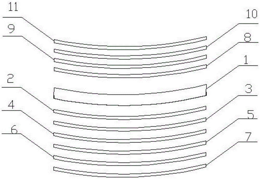
[0021] Such as figure 1 As shown, an anti-blue light optical lens includes: a substrate 1, a front composite anti-blue light film layer and a reverse surface composite anti-blue light film layer located on the front and back sides of the substrate, and the front composite anti-blue light film layer is sequentially arranged from inside to outside Including: first silicon monoxide layer 2, antimony oxide layer 3, first silicon dioxide layer 4, first tin oxide / ceria / palladium / platinum composite layer 5, second silicon dioxide layer 6, first fluorine Potassium oxide layer 7; the reverse composite anti-blue light film layer includes: the second silicon monoxide layer 8, the second tin oxide / ceria / palladium / platinum composite layer 9, the third silicon dioxide layer 10 , the second potassium fluoride layer 11 .
[0022] The mass average ratio of tin oxide, ceria, palladium, platinum in the first tin oxide / ceria / palladium / platinum composite layer and the second tin ox
Embodiment 2
[0026] Such as figure 1 As shown, the anti-blue light optical lens includes: a substrate 1, a front composite anti-blue light film layer and a reverse composite anti-blue light film layer located on the front and back sides of the substrate, and the front composite anti-blue light film layer sequentially includes from the inside to the outside: First silicon monoxide layer 2, antimony oxide layer 3, first silicon dioxide layer 4, first tin oxide / cerium oxide / palladium / platinum composite layer 5, second silicon dioxide layer 6, first potassium fluoride Layer 7; the reverse composite anti-blue light film layer includes: the second silicon monoxide layer 8, the second tin oxide / ceria / palladium / platinum composite layer 9, the third silicon dioxide layer 10, the second Potassium difluoride layer 11 .
[0027] The mass average ratio of tin oxide, ceria, palladium, platinum in the first tin oxide / ceria / palladium / platinum composite layer and the second tin oxide / ceri
Embodiment 3
[0031] Such as figure 1 As shown, the anti-blue light optical lens includes: a substrate 1, a front composite anti-blue light film layer and a reverse composite anti-blue light film layer located on the front and back sides of the substrate, and the front composite anti-blue light film layer sequentially includes from the inside to the outside: First silicon monoxide layer 2, antimony oxide layer 3, first silicon dioxide layer 4, first tin oxide / cerium oxide / palladium / platinum composite layer 5, second silicon dioxide layer 6, first potassium fluoride Layer 7; the reverse composite anti-blue light film layer includes: the second silicon monoxide layer 8, the second tin oxide / ceria / palladium / platinum composite layer 9, the third silicon dioxide layer 10, the second Potassium difluoride layer 11 .
[0032] The mass average ratio of tin oxide, ceria, palladium, platinum in the first tin oxide / ceria / palladium / platinum composite layer and the second tin oxide / ceri
PUM
| Property | Measurement | Unit |
|---|---|---|
| Film thickness | aaaaa | aaaaa |
| Thickness | aaaaa | aaaaa |
| Thickness | aaaaa | aaaaa |
Abstract
Description
Claims
Application Information
 - R&D Engineer
- R&D Manager
- IP Professional
- Industry Leading Data Capabilities
- Powerful AI technology
- Patent DNA Extraction
Browse by: Latest US Patents, China's latest patents, Technical Efficacy Thesaurus, Application Domain, Technology Topic.
© 2024 PatSnap. All rights reserved.Legal|Privacy policy|Modern Slavery Act Transparency Statement|Sitemap