Anhydrous deodorant aerosol equipped with a hollow dispensing head

A technology of dispensing head and dispensing hole is applied in the field of dispensing head to achieve the effect of simple structure and reliable function

Inactive Publication Date: 2016-02-24
LOREAL SA
View PDF13 Cites 0 Cited by
  • Summary
  • Abstract
  • Description
  • Claims
  • Application Information

AI Technical Summary

Benefits of technology

This technology makes it possible for small amounts of liquid material (such as paint) to quickly spread out on surfaces without getting stuck or damaging them during use. It also simplifies the mechanism used to control how much fluid needs to go through while still being able to deliver evenly over all areas with minimal pressure loss. Additionally, this system has several technical features such as easy-to-use components, durability against damage from external factors like rainwater, snowblows, etc., and appealing visual designs that appeal to customers' preferences.

Problems solved by technology

This patented describes different types of nozzles used on spray devices such as atomizers. These include drop generators (or distributor) without any openings but they still require some sort of pressure to deliver liquid through them properly. However, these designs can lead to overpressure when trying to achieve good results due to their shape being designed based only upon how well it works.

Method used


Image

  • Anhydrous deodorant aerosol equipped with a hollow dispensing head
  • Anhydrous deodorant aerosol equipped with a hollow dispensing head
  • Anhydrous deodorant aerosol equipped with a hollow dispensing head

Examples


Embodiment Construction

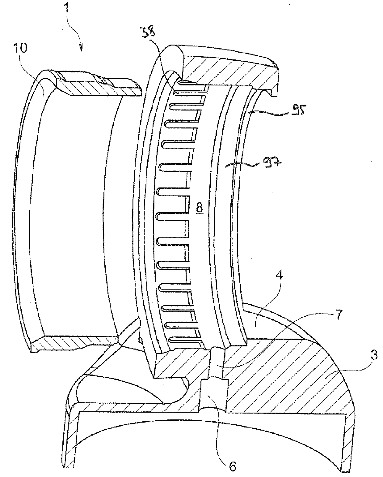
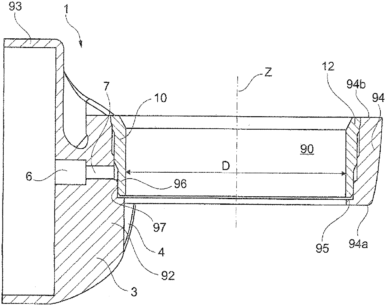
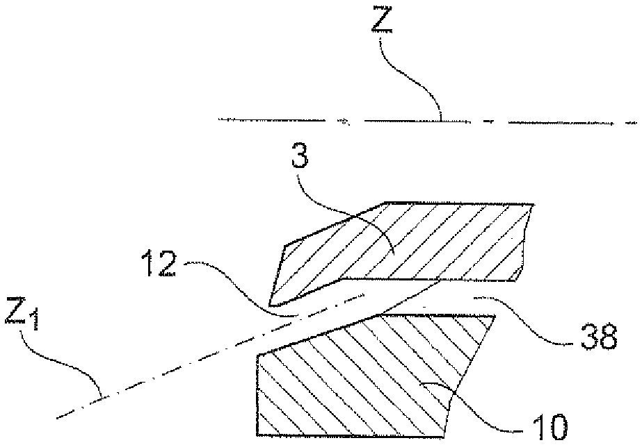
[0150] Figure 1 to Figure 3 The shown dispensing head 1 is intended to fit on a container not shown, which is provided with a hollow valve stem or pump rod through which the product to be dispensed contained in the container is directed towards the dispensing head 1 .

[0151] The container can in particular be a pressurized container of the aerosol canister type containing a propellant gas, for example compressed air or liquefied gas.

[0152] The container can be provided with a valve, and the opening of the valve can take place, for example, by insertion of the hollow rod or alternatively by turning it over. In case the container is equipped with a pump, the actuation of the pump can take place, for example, by the insertion of a hollow rod along its longitudinal axis.

[0153] The dispensing head 1 comprises a body 3 which can be made in one piece from a single piece, or comprise a plurality of elements which are manufactured separately and assembled together.

[0154] lik


PUM


Abstract

The invention relates to a device for dispensing a cosmetic composition, comprising a dispensing head (1) intended for a container housing the cosmetic composition to be dispensed, in which: (i) the dispensing head comprises: a body (3) open at its two opposing axial ends, and a co-operating part (10) open at its two opposing axial ends, defining at least partially at least one dispensing port (12), the cross-section of the dispensing port being between 0.05 mm2 and 0.5 mm2; and (ii) the anhydrous cosmetic composition comprises, in a cosmetically acceptable medium, at least one oily phase comprising one or more oils selected from among silicone, hydrocarbon and fluorinated oils, and at least one cosmetic active agent, in particular at least one deodorant active agent and/or an antiperspirant active agent.

Description


Claims


Application Information

Patent Timeline
Owner LOREAL SA
Why Eureka
Try Eureka