Mould and method for manufacturing hydrogen fuel cell module used as demonstration teaching aid and cell module

A fuel cell and battery module technology, which is applied in the direction of educational appliances, teaching models, instruments, etc., can solve problems such as time-consuming, long production time, and low production efficiency, and achieve the effects of improving production efficiency, adding functions, and enriching types

Inactive Publication Date: 2016-04-20
JUNJI ENERGY TECH CO LTD
View PDF7 Cites 4 Cited by
  • Summary
  • Abstract
  • Description
  • Claims
  • Application Information

AI Technical Summary

Benefits of technology

This technology helps produce batteries quickly while also adding more features like an improved catalyst or added functionality for better performance.

Problems solved by technology

This patented technical problem addressed in this patents relates to improving the process flow of producing batteries used at home or school levels due to their high cost compared to other methods such as liquid-based systems like lithium ion technology (LIB). Current ways involve manually combining multiple components together but these processes take longer than necessary because each component needs to align correctly before being pressed onto another part.

Method used


Image

  • Mould and method for manufacturing hydrogen fuel cell module used as demonstration teaching aid and cell module
  • Mould and method for manufacturing hydrogen fuel cell module used as demonstration teaching aid and cell module
  • Mould and method for manufacturing hydrogen fuel cell module used as demonstration teaching aid and cell module

Examples


Embodiment

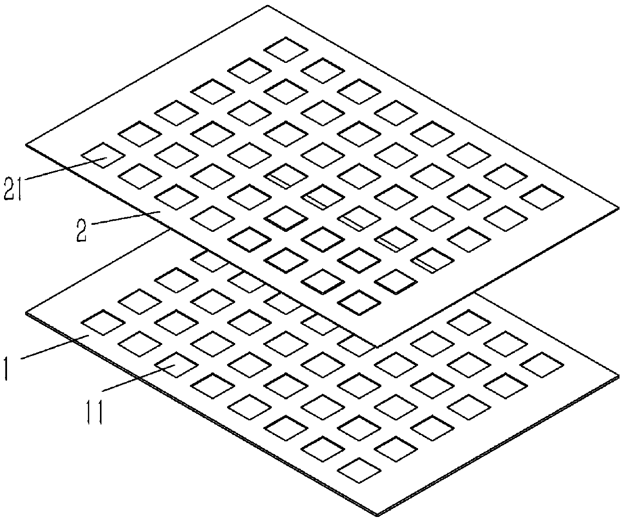
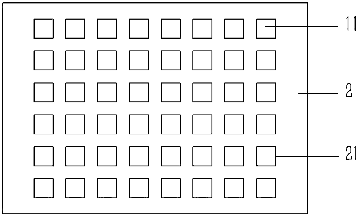
[0025] Example: see Figures 1 to 6 As shown, the mold for making a hydrogen fuel cell module for demonstration teaching aids includes a lower template 1 and an upper template 2. Several rectangular positioning grooves 11 are formed on the upper end surface of the lower template 1, and several rectangular positioning grooves 11 are formed on the upper template 2. The rectangular positioning hole 21 opposite to the positioning groove 11 of the template 1, one side of the upper template 2 and one side of the lower template 1 are fixed together.

[0026] The positioning grooves 11 are linearly and uniformly distributed on the lower template 1, and the positioning holes 21 are linearly and uniformly distributed on the upper template 2; equal.

[0027] The length and width of the lower template 1 are respectively equal to the length and width of the upper template 2 , and the depth of the positioning groove 11 on the lower template 1 is equal to the thickness of the upper template 2


PUM


Abstract

The invention discloses a mould for manufacturing a hydrogen fuel cell module used as a demonstration teaching aid. The mould comprises a lower mould plate (1) and an upper mould plate (2); a plurality of rectangular positioning grooves (11) are formed in the upper end surface of the lower mould plate (1); a plurality of rectangular positioning holes (21) opposite to the positioning grooves (11) in the lower mould plate (1) are formed in the upper mould plate (2); one side edge of the upper mould plate (2) is fixed with one side edge of the lower mould plate (1). An auxiliary mould and a new method for producing the cell module through the auxiliary mould are designed, the production time of the cell module is shortened, and the production efficiency of the cell module is improved.

Description


Claims


Application Information

Patent Timeline
Owner JUNJI ENERGY TECH CO LTD
Why Eureka
Try Eureka