Numerically-controlled brake cam shaft grinding machine

A technology of CNC grinding machines and mechanical devices, applied in the direction of grinding drive devices, grinding machines, abrasive belt grinding machines, etc., can solve the problems of parts processing accuracy, increase production costs, and high prices, and achieve the effect of improving processing accuracy

Active Publication Date: 2016-07-20
QUANZHOU LICHENG FUHUI AUTOMOBILE PARTS CO LTD
View PDF5 Cites 1 Cited by
  • Summary
  • Abstract
  • Description
  • Claims
  • Application Information

AI Technical Summary

Benefits of technology

This new design allows for better precision when machining materials by utilizing both electricity from one side (the machine's drive) and pressure applied through another part called an anchor rod. By doing these things together, it ensures accurate results even during movement between different directions without any gaps caused by constantly applying forces.

Problems solved by technology

Technics: Mechanic Profile Forming Grinders (MPG) were developed during early stages but they had limitations such as being expensive and requiring frequent maintenance because their manufacturing processes resulted in worn-out surfaces. To address these issues, there was an effort put into developing new types of milling systems called Braking Cam Shifters(BSC). These improvements aim to improve upon existing methods like mechanically profiling grinds, reducing cost and improving productivity.

Method used


Image

  • Numerically-controlled brake cam shaft grinding machine
  • Numerically-controlled brake cam shaft grinding machine

Examples


Embodiment Construction

[0011] The following will clearly and completely describe the technical solutions in the embodiments of the present invention with reference to the accompanying drawings in the embodiments of the present invention. Obviously, the described embodiments are only some, not all, embodiments of the present invention. Based on the embodiments of the present invention, all other embodiments obtained by persons of ordinary skill in the art without making creative efforts belong to the protection scope of the present invention.

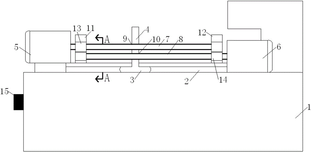
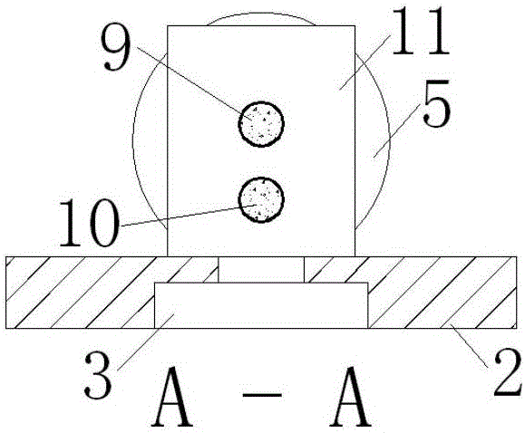
[0012] see Figure 1-2 , the present invention provides a technical solution: a mechanical device for a brake camshaft CNC grinder, including a grinder body 1, on which a horizontal guide rail 2 is installed on the grinder body 1, a slider 3 is installed in the guide rail 2, and the slider 3 The upper end is provided with a fixture support plate 4, and the left and right ends of the grinding machine body 1 are respectively provided with two opposite left motors 5


PUM


Abstract

The invention discloses a numerically-controlled brake cam shaft grinding machine. A right lead screw is rotationally connected with a right support plate through a right bearing; a controller is mounted on a grinding machine body; and both a left motor and a right motor are electrically connected with the controller. According to the numerically-controlled brake cam shaft grinding machine, the two motors are arranged at the left end and the right end of a guide rail respectively; when rightward movement is performed, the right threaded end surface of the left lead screw is a main stress surface, the right motor stays in a silent state, and the left threaded end surface of the right lead screw is a main stress surface; and when leftward movement is performed, the left motor stays in a silent state, the right threaded end surface of the left lead screw is the main stress surface, and the left threaded end surface of the right lead screw is the main stress surface. Therefore, whether leftward movement or right movement is performed, the right threaded end surface of the left lead screw and the left threaded end surface of the right lead screw are the main stress surfaces, so that no gap is produced when the lead screws are stressed always, and the part machining precision is greatly improved.

Description


Claims


Application Information

Patent Timeline
Owner QUANZHOU LICHENG FUHUI AUTOMOBILE PARTS CO LTD
Why Eureka
Try Eureka