Voltage feedback-based white LED oscillatory efficiency drive system

A voltage feedback, high-efficiency driving technology, applied in electric light sources, electroluminescent light sources, light sources, etc., can solve the problems of high energy consumption and low driving efficiency, and achieve the effects of low power consumption, high driving efficiency, and improved stability.

Inactive Publication Date: 2016-07-27
CHENGDU SIBOTE TECH CO LTD
View PDF0 Cites 1 Cited by
  • Summary
  • Abstract
  • Description
  • Claims
  • Application Information

AI Technical Summary

Problems solved by technology

[0003] The purpose of the present invention is to overcome the defects of low drive efficiency and high energy consumption in the traditional LED drive circuit, and provide a high-efficiency drive system for white LED oscillation based on voltage feedback

Method used


Image

  • Voltage feedback-based white LED oscillatory efficiency drive system
  • Voltage feedback-based white LED oscillatory efficiency drive system
  • Voltage feedback-based white LED oscillatory efficiency drive system

Examples


Example Embodiment

[0021] Example

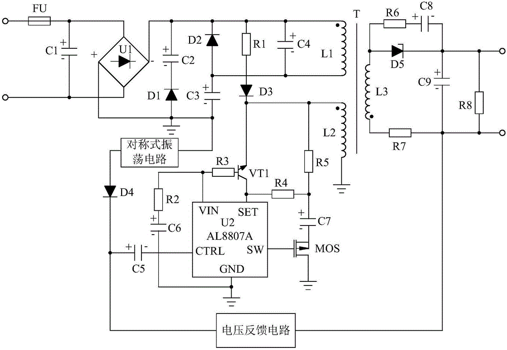
[0022] Such as figure 1 As shown, the white LED oscillation high-efficiency drive system based on voltage feedback of the present invention is mainly composed of transformer T, power supply circuit, microprocessor circuit, symmetrical oscillation circuit, high-efficiency step-down drive circuit, voltage feedback circuit and secondary output The circuit consists of seven parts.

[0023] Such as figure 1 As shown, the microprocessor circuit is connected in series between the primary inductor coil L1 of the transformer T and the power supply circuit, the symmetrical oscillation circuit is connected to the power supply circuit, and the high-efficiency step-down drive circuit is connected to the symmetrical oscillation circuit and The micro-processing circuit is connected, the secondary output circuit is connected to the secondary inductor L3 of the transformer T, and the voltage feedback circuit is connected in series between the secondary output circuit and the high-effi


PUM


Abstract

The invention discloses a voltage feedback-based white LED oscillatory efficiency drive system, characterized by mainly comprising: a transformer T, a power supply circuit, a microprocessing circuit serially connected between a primary side inductance coil L1 of the transformer T and the power supply circuit, a symmetric oscillating circuit connected with the power supply circuit, an efficient step-down drive circuit connected with both the symmetric oscillating circuit and the microprocessing circuit, a secondary side output circuit connected with an auxiliary side inductance coil L3 of the transformer T and the like.A voltage feedback circuit is set herein and can acquire output voltage of the drive system and feed back to the efficient step-down drive circuit so that the efficient step-down circuit can adjust its output voltage according to the fed-back voltage; therefore, a closed-loop control system is formed herein, and the drive system and LEE can be protected.

Description


Claims


Application Information

Patent Timeline
Owner CHENGDU SIBOTE TECH CO LTD
Why Eureka
Try Eureka