Segmented heating and cooling quenching process for wheel body of thrust wheel

A technology of segmental heating and support rollers, which is applied in the direction of quenching agent, quenching device, process efficiency improvement, etc., can solve the problems of slow and uneven quenching speed of support rollers, deformation and cracking hardness, etc., achieve uniform cooling, improve The effect of induction heating speed and uniform hardness

Active Publication Date: 2016-08-03
KUSN KENSETABU BUHIN
View PDF2 Cites 2 Cited by
  • Summary
  • Abstract
  • Description
  • Claims
  • Application Information

AI Technical Summary

Benefits of technology

This patented technology describes various ways to improve the performance or durability of steel rolling mill bearings used during their production processes such as lubrication systems. It involves improving the cool down period (the slower pace), reducing cracks caused due to stress corrosion cracking (SCC). Additionally, introducing an inductive heating system can help prevent damage from excess pressure applied over them without causing too much strain. Overall, these improvements enhance the overall effectiveness and longevity of bearing components in industrial applications like steel rolling machines.

Problems solved by technology

This patented technical problem addressed in this patents relates to improving the performance of railroad equipment's tracks during operation due to their heavy load carrying capabilities. Track rollers require high levels of durability with minimal damage caused from external factors like impact loads and abrasion over long periods without losing functionality. However, current methods involve adding layers made up mostly of materials called chrome plating onto support wheels, resulting in weakened areas where cracks may occur easily. Additionally, there was no efficient way to efficiently use liquid nitrogen (LN2) instead of air because LNG requires much more energy compared to other fluids.

Method used


Image

  • Segmented heating and cooling quenching process for wheel body of thrust wheel
  • Segmented heating and cooling quenching process for wheel body of thrust wheel
  • Segmented heating and cooling quenching process for wheel body of thrust wheel

Examples


Embodiment 1

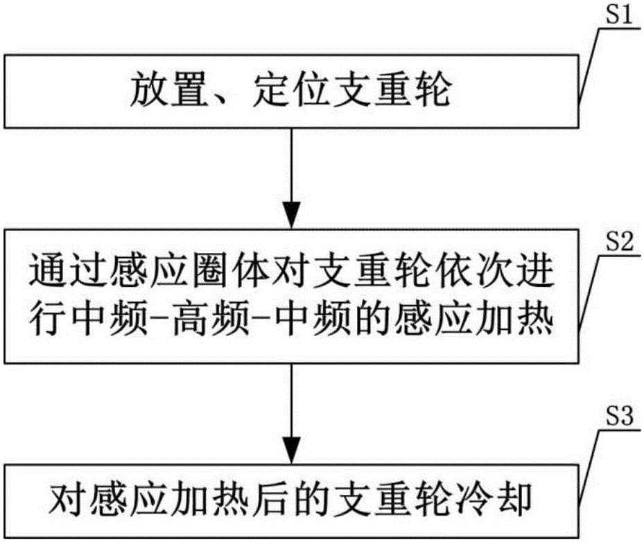
[0043] figure 1 It is the flow chart of the segmental heating, cooling and quenching process of the roller body of the present invention, consisting of figure 2 It can be seen that the segmental heating, cooling and quenching process of the roller body includes the following steps:

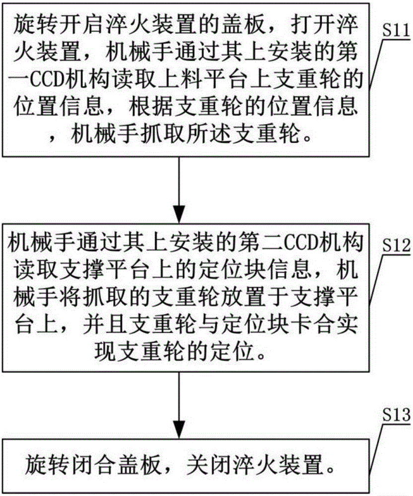
[0044] S1, placing and positioning the rollers: grab the rollers by the manipulator and place them on the supporting platform in the quenching device;

[0045] S2, through the induction coil body, carry out the induction heating of intermediate frequency-high frequency-intermediate frequency on the supporting wheel in sequence;

[0046] S3, cooling the track rollers after induction heating: performing water-salt water-oil spray cooling on the track rollers after induction heating in sequence.

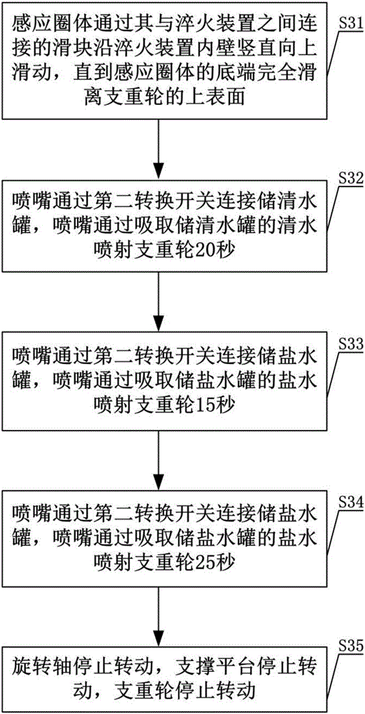
[0047] Among them, such as figure 2 As shown, step S3 specifically includes the following steps:

[0048] S31, the induction coil body slides vertically upwards along the inner wall of the quenching devi

Embodiment 2

[0063] On the basis of Embodiment 1, this embodiment provides an implementation of step S2, such as Figure 4 As shown, step S2 specifically includes the following steps:

[0064] S21, set the induction coil body with the same shape as the track roller on the outer side of the track roller, and there is a gap between the induction coil body and the track roller, and the gap is 1 mm;

[0065] S22, the rotating shaft connected under the horizontal center of the support platform rotates to drive the support platform to rotate, and the support platform rotates to drive the rollers to rotate;

[0066] S23, the induction coil body is connected to the medium-frequency induction heating power supply through the first switch, and the supporting wheels are evenly heated to a temperature of 500°C±20°C at the same time, and kept for 20 seconds;

[0067] S24, the induction coil body is connected to the high-frequency induction heating power supply through the first transfer switch, and the s


PUM

PropertyMeasurementUnit
Hardnessaaaaaaaaaa

Abstract

The invention discloses a segmented heating and cooling quenching process for a wheel body of a thrust wheel. The process comprises the following steps of 1, placing and positioning the thrust wheel, wherein the thrust wheel is grabbed through a mechanical arm and placed on a support platform in a quenching device; 2, sequentially conducting intermediate frequency, high frequency and intermediate frequency induction heating on the thrust wheel through induction coil bodies; 3, cooling the thrust wheel obtained after induction heating, wherein spray cooling implemented through water, saline water and oil is sequentially conducted on the thrust wheel obtained after induction heating. According to the thrust wheel quenching process, the water-saline water-quenching oil cooling process is adopted, so that the problems that in the prior art, the quenching speed of a thrust wheel is low, the thrust wheel is deformed and cracked, and the thrust wheel is inconsistent in hardness after being quenched; the quenching process has the advantages of being uniform in thrust wheel hardness and high in quenching efficiency.

Description


Claims


Application Information

Patent Timeline
Owner KUSN KENSETABU BUHIN
Why Eureka
Try Eureka