Lamp core of LED light bar lamp and manufacturing method of lamp core

A technology for LED light bars and light bar lights, which is applied in the manufacture of printed circuits, lighting and heating equipment, and components of lighting devices, etc., can solve the problems of low welding efficiency, high production costs, and inconvenient assembly of lamp wicks. Low cost, high assembly efficiency, easy automatic welding effect

Inactive Publication Date: 2016-09-21
SHENZHEN CRYSTAL PORCELAIN PHOTOELECTRIC CO LTD
View PDF5 Cites 0 Cited by
  • Summary
  • Abstract
  • Description
  • Claims
  • Application Information

AI Technical Summary

Problems solved by technology

However, the wick of this full-circle dimmable LED lamp is not easy to assemble, the welding efficiency is low, and the production cost is high.

Method used


Image

  • Lamp core of LED light bar lamp and manufacturing method of lamp core
  • Lamp core of LED light bar lamp and manufacturing method of lamp core
  • Lamp core of LED light bar lamp and manufacturing method of lamp core

Examples


Example Embodiment

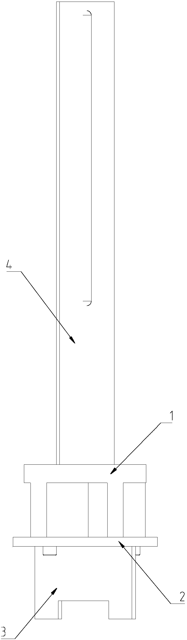
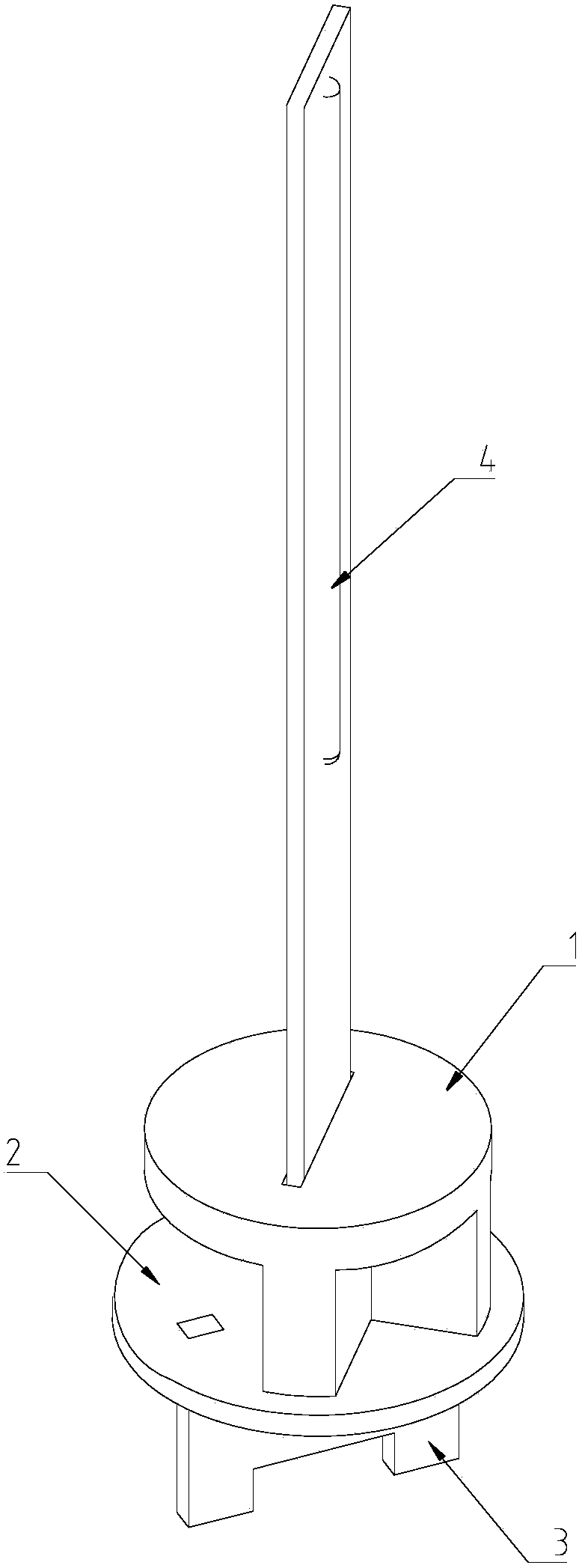
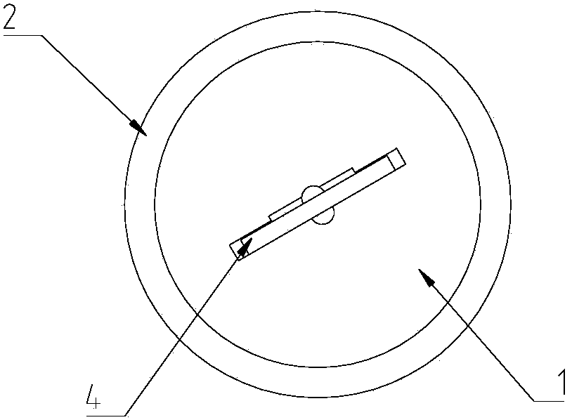
[0045] The structure of the wick of embodiment 1 of the present invention is as follows Figure 1 to Figure 11 As shown, it includes a bracket 1, a circuit connection board 2, a power supply board 3 and an LED light bar 4.

[0046] The LED light bar 4 is a double-sided light bar, including a glass substrate 401, an LED light string 402 arranged on both sides of the glass substrate 401, and two pads 403 arranged at the lower end of the glass substrate 401. The pads 403 pass through a printed circuit on the substrate 401 It is electrically connected to the LED light string 402.

[0047] The support 1 includes a plate body 101 and two vertical plates 102. The top end of the vertical plate 102 is connected to the bottom surface of the plate body 101, and the two vertical plates 102 are connected to each other. There is an elongated through hole 103 in the middle of the disc body 101, and two vertical plates 102 avoid the through hole 103. The vertical plate 102 arranged in the middle has


PUM


Abstract

The invention discloses a lamp core of an LED light bar lamp and a manufacturing method of the lamp core. The lamp core of the LED light bar lamp comprises a bracket, a circuit connecting board, a power board and at least one LED light bar, wherein two bonding pads are arranged at the lower end of each LED light bar, the bracket comprises through holes, and the number of the through holes is the same as that of the LED light bars; two bonding pads electrically connected with each light bar are arranged on the top surface of the circuit connecting board, and two bonding pads electrically connected with the power board are arranged on the bottom surface of the circuit connecting board; a plurality of bolts are arranged at the lower end of the bracket, the circuit connecting board comprises a plurality of bolt holes and two slots, and the bolts are inserted into the bolt holes; two inserting tenons are arranged at the top end of the power board and are inserted into the slots of the circuit connecting board; the lower end of each LED light bar penetrates through the corresponding through hole in the bracket, and the bonding pads of each LED light bar are welded with the bonding pads on the top surface of the circuit connecting plate; two bonding pads are arranged at the upper end of the power board, and the bonding pads at the upper end of the power board are welded with the bonding pads on the bottom surface of the circuit connecting board. The lamp core of the LED light bar lamp facilitates automatic welding and is high in assembling efficiency and low in production cost.

Description


Claims


Application Information

Patent Timeline
Owner SHENZHEN CRYSTAL PORCELAIN PHOTOELECTRIC CO LTD
Why Eureka
Try Eureka