Reaction system for increasing utilization ratio of reactants in chloromethane production and application of reaction system
A technology of reaction system and methyl chloride, applied in the field of reaction system, can solve the problems of underutilization of reaction raw materials and complex arrangement of equipment, etc., and achieve the effect of easy control of the reaction process, simple arrangement and high purity
- Summary
- Abstract
- Description
- Claims
- Application Information
AI Technical Summary
Problems solved by technology
Method used
Image

Examples
Embodiment 1
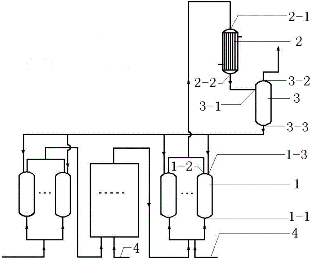
[0026] A reaction system for improving the utilization rate of reactants in the production of methyl chloride, comprising a reaction unit, a condenser 2 and a reflux tank 3, said reaction unit comprising 2 reactors 1 connected in series, each reactor 1 at the bottom Reactor inlet I1-1 is provided with, and the top of each reactor 1 is provided with reactor outlet 1-2 and reactor inlet II 1-3, and the outlet of reaction unit (that is: the second The reactor discharge port 1-2) of each reactor 1 is connected with the condenser feed port 2-1 of the condenser 2, and the condenser discharge port 2-2 of the condenser 2 is fed with the reflux tank feed port of the reflux tank 3 Port 3-1 is connected, and the top and bottom of the reflux tank 3 are respectively provided with a reflux tank discharge port I 3-2 and a reflux tank discharge port II 3-3, and the reflux tank discharge port II 3-3 of the reflux tank 3 -3 are connected to the reactor feed port II 1-3 of each reactor 1 respective
Embodiment 2
[0028] A reaction system for improving the utilization rate of reactants in the production of methyl chloride, comprising a reaction unit, a condenser 2 and a reflux tank 3, the reaction unit includes 5 reactors 1 connected in series, and each reactor 1 is also connected in parallel There is one reactor 1; the bottom end of each reactor 1 is provided with a reactor feed port I 1-1, and the top of each reactor 1 is provided with a reactor feed port 1-2 and a reactor feed port II 1-3, the discharge port of the reaction unit (that is: the reactor discharge port 1-2 of the last series reactor 1) is connected with the condenser feed port 2-1 of the condenser 2, and the condenser 2 Condenser discharge port 2-2 is connected with reflux tank feed port 3-1 of reflux tank 3, and the top and bottom of reflux tank 3 are respectively provided with reflux tank discharge port I 3-2 and reflux tank discharge port II 3-3, the reflux tank outlet II 3-3 of the reflux tank 3 is connected to the reac
Embodiment 3
[0030] A reaction system for improving the utilization rate of reactants in the production of methyl chloride, comprising a reaction unit, a condenser 2 and a reflux tank 3, the reaction unit includes 3 reactors 1 connected in series, and each reactor 1 is also connected in parallel There are 2 reactors 1; the bottom of each reactor 1 is provided with a reactor feed port I 1-1, and the top of each reactor 1 is provided with a reactor feed port 1-2 and a reactor feed port II 1-3, the reactor feed port I 1-1 of each reactor 1 is also provided with bypass pipeline 4; 1-2) It is connected with the condenser feed port 2-1 of the condenser 2, the condenser discharge port 2-2 of the condenser 2 is connected with the reflux tank feed port 3-1 of the reflux tank 3, and the reflux tank 3 The top and the bottom end are respectively provided with a reflux tank discharge port I 3-2 and a reflux tank discharge port II 3-3, and the reflux tank discharge port II 3-3 of the reflux tank 3 is conne
PUM
 Abstract
Description
Claims
Application Information
 - R&D Engineer
- R&D Manager
- IP Professional
- Industry Leading Data Capabilities
- Powerful AI technology
- Patent DNA Extraction
Browse by: Latest US Patents, China's latest patents, Technical Efficacy Thesaurus, Application Domain, Technology Topic.
© 2024 PatSnap. All rights reserved.Legal|Privacy policy|Modern Slavery Act Transparency Statement|Sitemap