Locking device used for inertial measurement unit rotating mechanism

A technology of rotating mechanism and locking device, which is applied in the direction of fixing devices, mechanical equipment, etc., can solve the problems of poor stability and consistency of inertial group positions, affecting locking accuracy functions, and decreased guiding accuracy, so as to achieve stability and consistency Good, reduce the unlocking force requirements and reduce the effect of instantaneous collision force

Active Publication Date: 2016-11-02
HUNAN AEROSPACE ELECTROMECHANICAL EQUIP & SPECIAL MATERIAL INST
View PDF5 Cites 0 Cited by
  • Summary
  • Abstract
  • Description
  • Claims
  • Application Information

AI Technical Summary

Benefits of technology

This patented technology helps prevent damage from shocks or other factors affecting the mechanism used during locks made up of two springs. It uses an interference fit with teeth on both parts instead of just one flat surface, which makes sure they stay securely fixed together even if some play occurs over time. Additionally, this design allows for precise guidance when inserting bolts into holes without causing any problems such as excessive pressure at certain points along its length. Overall, these technical features improve safety performance while reducing energy consumption compared to existing systems.

Problems solved by technology

Technic problem addressed in this patents relates to improving the performance or reliability of an inkjet printer's motion control system due to issues such as gaps that can cause instabilities during operation caused by imperfections on the interface surfaces themselves (such as abrasion) and lack of sufficient flexibility when fitting different components together without causing damage).

Method used


Image

  • Locking device used for inertial measurement unit rotating mechanism
  • Locking device used for inertial measurement unit rotating mechanism
  • Locking device used for inertial measurement unit rotating mechanism

Examples


Embodiment Construction

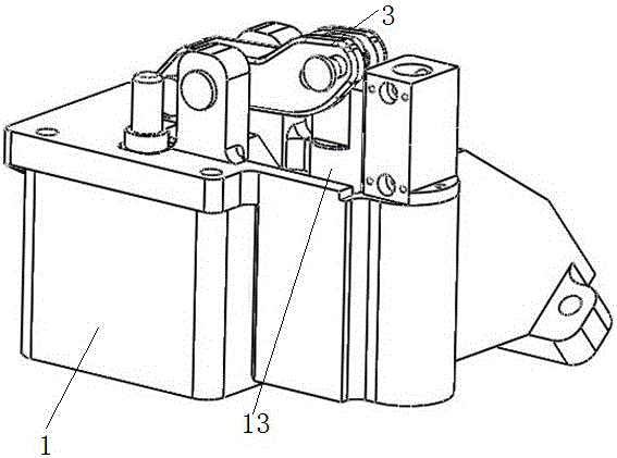
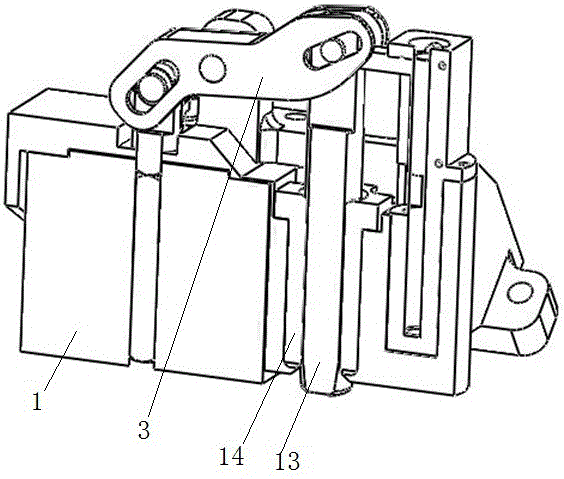
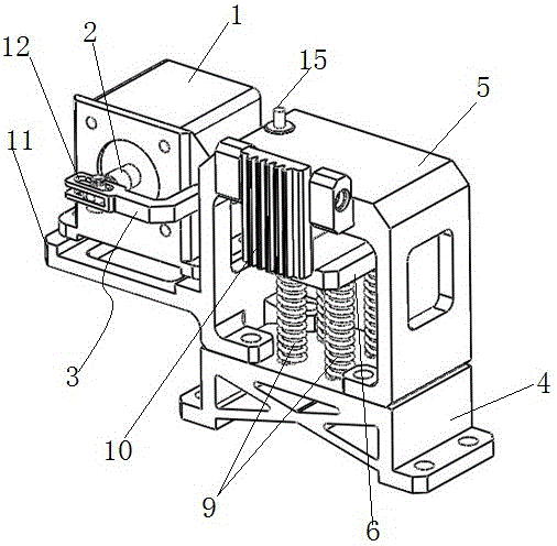
[0041] Such as Figure 3-9 As shown, a locking device for an inertial group rotating mechanism includes a linear motor 1, a lever 3 hinged to the linear motor shaft 2, and a locked part on the rotating mechanism. The lever 3 is provided with a waist-shaped groove 12 at the hinge joint with the linear motor shaft 2, and the linear motor shaft 2 can slide in the waist-shaped groove 12 of the lever 3.

[0042] It also includes a base 4, a hollow bracket 5 installed on the base 4, a locking member that can move horizontally and linearly on the top of the inner cavity of the bracket 5, and a movable guide 6 for supporting the bottom of the locking member. The motor mounting seat 11 is also included, and the motor mounting seat 11 and the bracket 5 are integrally formed.

[0043] The locking member is hinged to the other end of the lever 3, and the locking member and the locked member can be fixed in cooperation with each other. The fulcrum 15 of the lever 3 is located on the support 5.


PUM


Abstract

The invention discloses a locking device used for an inertial measurement unit rotating mechanism. The locking device used for the inertial measurement unit rotating mechanism comprises a linear motor, a lever which is hinged to a linear motor shaft and a locked part which is located on the rotating mechanism. The locking device used for the inertial measurement unit rotating mechanism further comprises a base, a hollow supporting frame which is mounted on the base, a locking part which is capable of moving horizontally in a straight line at the top of the inner cavity of the supporting frame and a movable guiding rail which is used for supporting the bottom of the locking part. The movable guiding rail is connected with the base by a supporting device which can float up and down. The locking part is hinged to the other end of the lever and the locking part and the locked part can be fixed by matching with each other. According to the locking device, the movable guiding rail is used for guiding and an elastic locking manner is used, so that the function of wear-self-compensation of the guiding rail and the function of locking-clearance-self-compensation can be realized and the requirement for the releasing force can be reduced.

Description


Claims


Application Information

Patent Timeline
Owner HUNAN AEROSPACE ELECTROMECHANICAL EQUIP & SPECIAL MATERIAL INST
Why Eureka
Try Eureka