Rotation material taking structure of die bonder

A die-bonding machine and die-bonding technology, which is used in conveyor objects, semiconductor/solid-state device manufacturing, electrical components, etc., can solve the problems of complex structure and high cost, and achieve the effect of ingenious structure, cost saving and compact structure.

Inactive Publication Date: 2016-11-16
深圳市朝阳光科技有限公司
View PDF3 Cites 0 Cited by
  • Summary
  • Abstract
  • Description
  • Claims
  • Application Information

AI Technical Summary

Problems solved by technology

[0003] The technical purpose of the present invention overcomes the technical problems of high cost and complex structure in the expected structure of

Method used


Image

  • Rotation material taking structure of die bonder
  • Rotation material taking structure of die bonder

Examples


Embodiment Construction

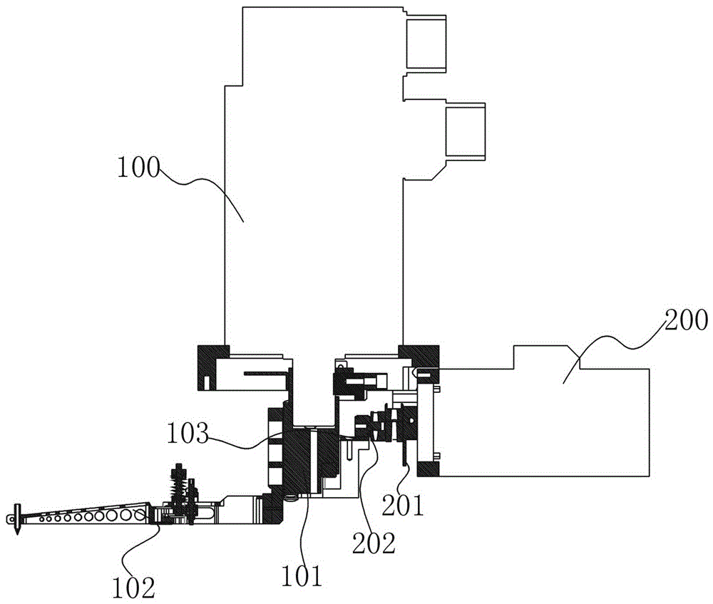
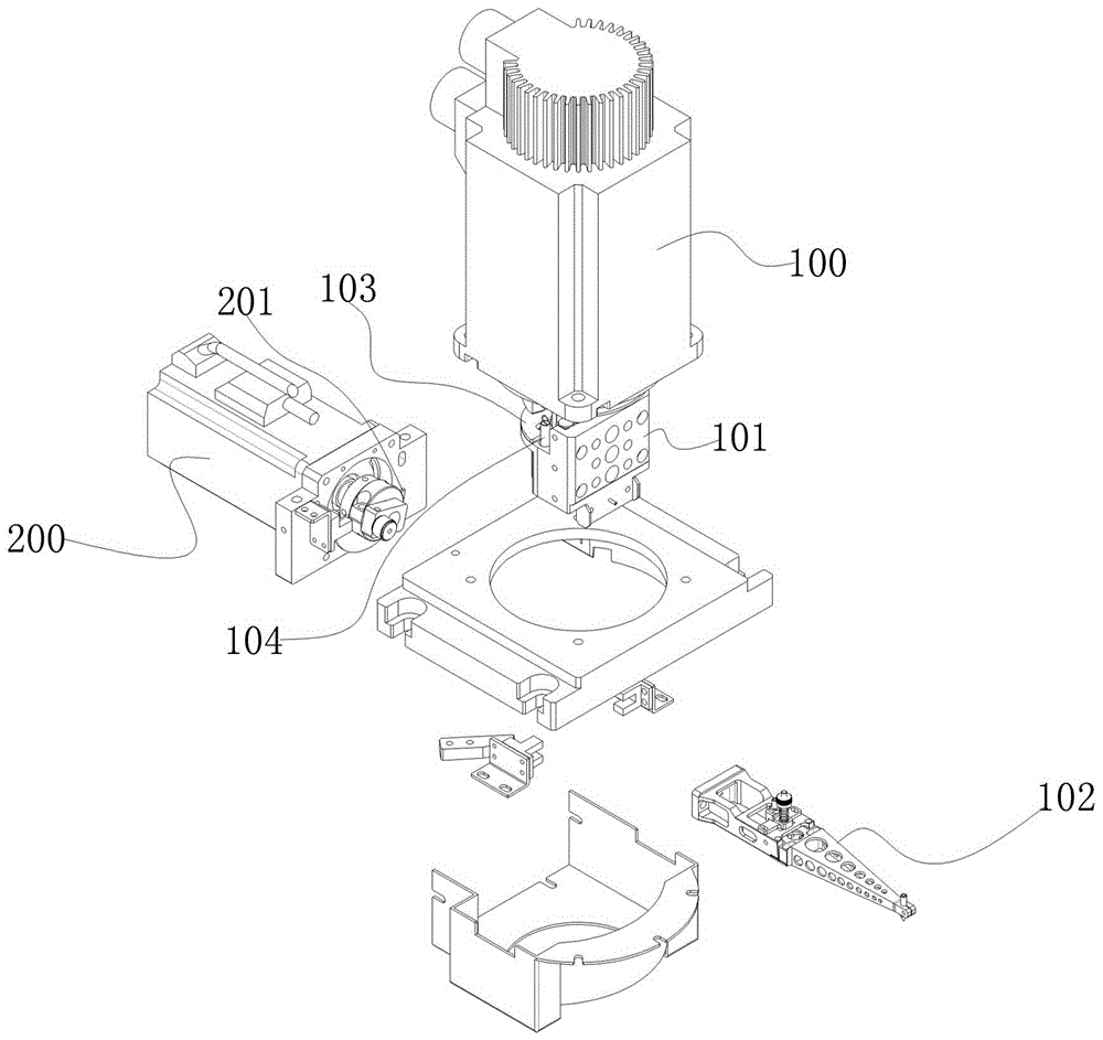
[0011] to combine figure 1 and figure 2 , which describes the specific implementation of the present invention in detail, but does not limit the claims in any way.

[0012] In the implementation of the present invention, the rotary reclaiming structure of the solid crystal machine includes a vertically arranged rotating motor 100, and a horizontally arranged lifting motor 200 is provided below the rotating motor 100; the motor of the lifting motor 200 A needle bearing 202 and a rotation induction piece 201 are arranged on the shaft, and the needle bearing 202 is connected with a lifting seat 101, which is arranged on the motor shaft of the rotating motor 100 and is driven to rotate by the rotating motor 100; the lifting seat 101 is connected with a crystal-bonding bracket 102 . The lifting seat 101 is provided with a wear-resistant plate 103, and a return spring 104 is arranged between the lifting seat 101 and the rotating motor 100, which is used to assist the lifting seat 10


PUM


Abstract

The invention provides a rotation material taking structure of a die bonder. The technical purpose of the invention is to provide the rotation material taking structure of a die bonder, an independent module is provided, and the assembling space is saved. The rotation material taking structure comprises a vertical rotation motor, and an elevating motor in a transverse arrangement is arranged under the rotation motor. The motor shaft of the elevating motor is provided with a needle bearing which is connected to an elevating seat, and the elevating seat is arranged on the motor shaft of the rotation motor and is driven by the rotation motor to rotate. The elevating seat is connected to a die bond bracket. The rotation material taking structure has the advantages of ingenious construction and cost saving, rotation and upper and lower componets are connected to the rotation motor shaft, the structure is compact, stable and reliable, and the rotation material taking structure is suitable for being applied to the production process of an LED.

Description


Claims


Application Information

Patent Timeline
Owner 深圳市朝阳光科技有限公司
Why Eureka
Try Eureka