Lightweight differential assembly

A differential and lightweight technology, which is applied in the direction of differential transmission, belt/chain/gear, mechanical equipment, etc., can solve the problem of increasing the axial length of the half shaft, increasing the weight of the left case of the differential, and increasing the weight of the right differential. Problems such as increased shell weight, to achieve the effect of increasing axial length, shortening length, reducing weight and cost

Inactive Publication Date: 2020-02-14
FAW JIEFANG AUTOMOTIVE CO
View PDF7 Cites 0 Cited by
  • Summary
  • Abstract
  • Description
  • Claims
  • Application Information

AI Technical Summary

Problems solved by technology

[0003] The present invention aims to solve the problem that in the existing automobile axles, since the differential bearing is installed on the shaft diameter of the differential case, the weight of the left case of the differential is

Method used


Image

  • Lightweight differential assembly
  • Lightweight differential assembly

Examples


Embodiment Construction

[0014] The present invention will be further elaborated in conjunction with the accompanying drawings.

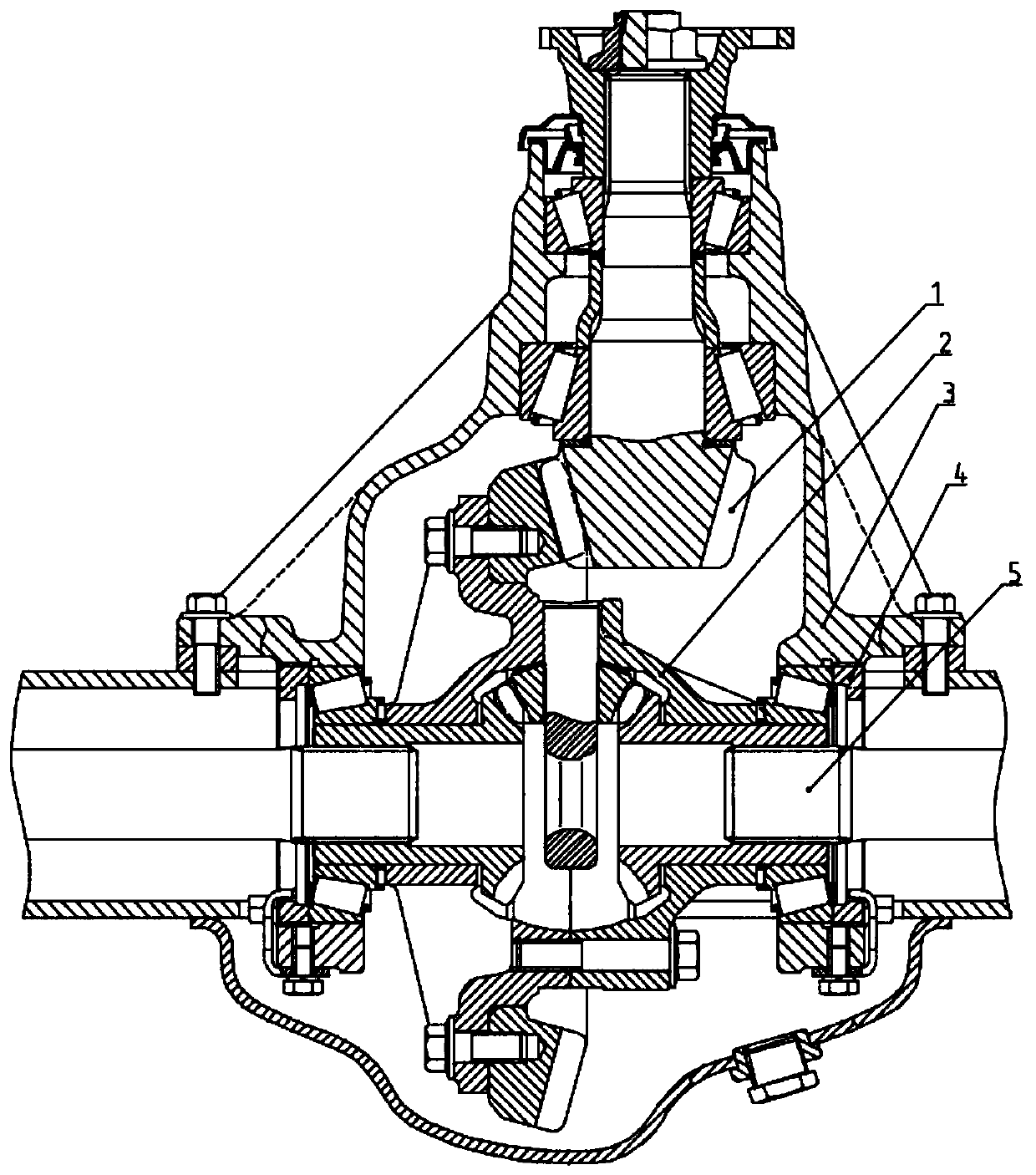
[0015] Such as figure 1 As shown, the lightweight differential assembly structure of the present invention is applied to the view of the rear axle assembly. The bevel teeth of the driven bevel gear 11 in the differential assembly 2 mesh with the bevel teeth of the driving bevel gear 1; Fitting; the end face of the adjusting ring 4 fits with the end faces of the two tapered roller bearings 6 in the differential assembly 2; the spline hole of the side gear 9 in the differential assembly 2 and the spline shaft of the half shaft 5 connect.

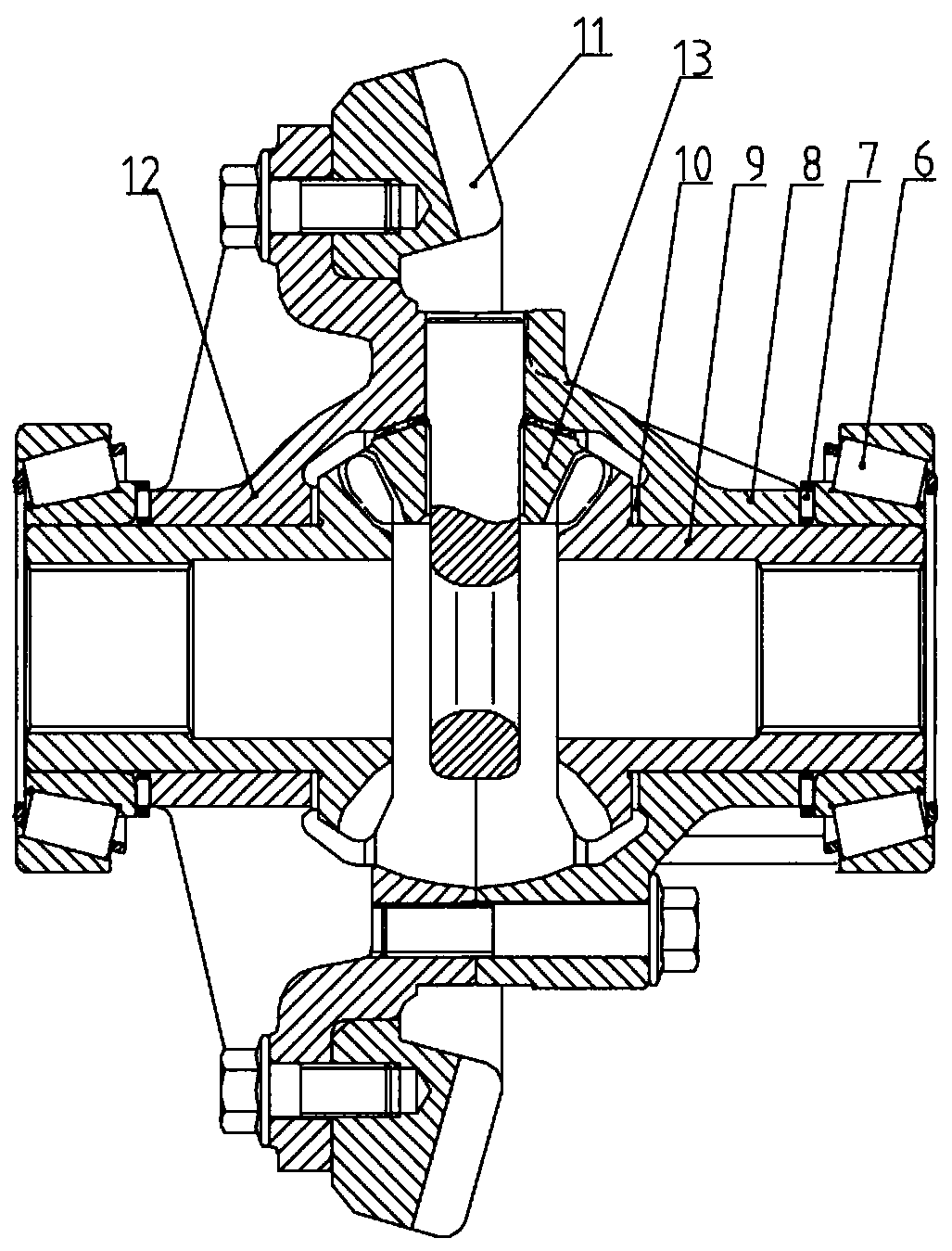
[0016] Such as figure 2 As shown, the shaft diameter of the side gear 9 matches the round hole of the differential right case 8, and the side gear spacer 10 is used between the shoulder plane of the side gear 9 and the plane of the differential right case 8, and the half shaft The bevel teeth of the shaft gear 9 mesh with the bevel teeth


PUM


Abstract

The invention relates to a lightweight differential assembly. The lightweight differential assembly adopts the structure that a differential bearing is mounted on the axle diameter of a half-axle gearinstead of the structure that the differential bearing is mounted on the axle diameter of a differential shell. By the adoption of the structure, the weight and cost of a left shell of a differentialare reduced, and the weight and cost of a right shell of the differential are reduced. According to the lightweight differential assembly, by increasing the axial length of the half-axle gears, the length of half axles is reduced, so that the weight and cost of the half axles are reduced; and a needle bearing set structure is adopted between differential bearings and the differential shells, andthe relative rotation reliability is guaranteed.

Description


Claims


Application Information

Patent Timeline
Owner FAW JIEFANG AUTOMOTIVE CO
Why Eureka
Try Eureka