Automatic reclosing circuit breaker
A technology for automatic reclosing and circuit breakers, applied to circuits, components of protective switches, electrical components, etc., to simplify electrical control and improve reliability
- Summary
- Abstract
- Description
- Claims
- Application Information
AI Technical Summary
Benefits of technology
Problems solved by technology
Method used
Image

Examples
Embodiment 1
[0038] Figure 1 to Figure 16 Show the first kind of specific embodiment of the present invention, below in conjunction with appendix Figure 1 to Figure 16 The present embodiment will be described in detail.
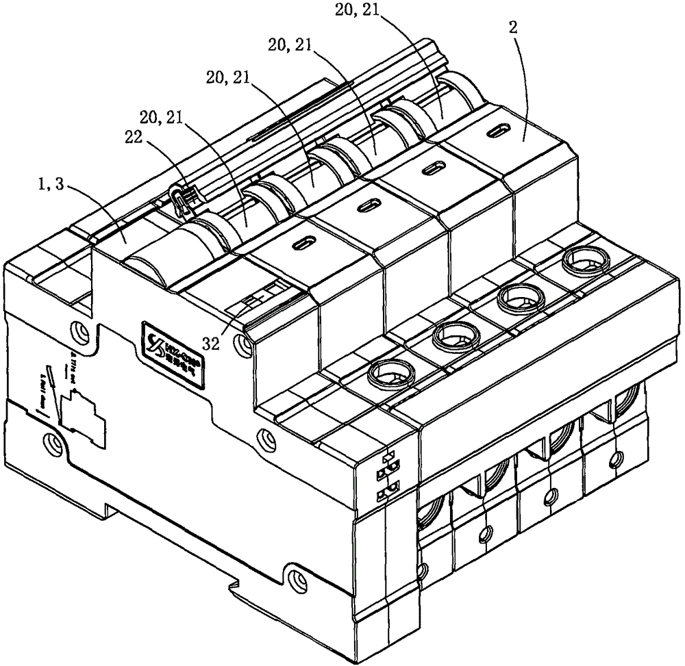
[0039] See figure 1As shown, this embodiment is an automatic reclosing circuit breaker, including a circuit breaker body 2 and an automatic reclosing drive mechanism 1; in this embodiment, the circuit breaker body 2 includes four miniature circuit breakers 20 (also called miniature circuit breakers) ). In practice, according to specific requirements, the number of miniature circuit breakers combined into the circuit breaker body can be arbitrarily selected from one to four.
[0040] Each miniature circuit breaker 20 includes a molded case 21, opening and closing handle 22, moving contact, static contact, operating mechanism, power input terminal, power output terminal and arc extinguishing mechanism; the rotation center of each opening and closing handle There is a mai
Embodiment 2
[0068] Figure 17 to Figure 19 A second embodiment of the invention is shown.
[0069] This embodiment is basically the same as Embodiment 1, the difference is: see Figure 17 to Figure 19 As shown, the vane switch assembly in this embodiment is no longer provided with the third stationary vane, but the second moving vane and the fourth stationary vane in Embodiment 1 are replaced by the third moving vane 931 and the fifth stationary vane respectively. 932, the third moving blade and the fifth stationary blade are combined to form a double-blade switch; in essence, the second three-blade switch in Embodiment 1 is replaced by the double-blade switch.
[0070] In this embodiment, the first stationary blade 911 , the first moving blade 912 , the second stationary blade 913 , the third moving blade 931 and the fifth stationary blade 932 are sequentially arranged around the circular through hole 90 in a clockwise direction. When the stirring boss rotates with the transmission turbin
Embodiment 3
[0074] Figure 20 A third embodiment of the invention is shown.
[0075] This embodiment is basically the same as Embodiment 1, the difference is: see Figure 20 As shown, the present embodiment no longer sets the first three-leaf switch and the second three-leaf switch, but uses three double-leaf switches instead, and these three double-leaf switches are respectively the first double-leaf switch 94 and the second double-leaf switch 94 switch 95 and the third double-blade switch 96; the first double-blade switch is provided with the sixth moving blade 941 and the sixth stationary blade 942; the second double-blade switch is provided with the seventh moving blade 951 and the seventh stationary blade 952; the third The double-blade switch is provided with an eighth moving blade 961 and an eighth stationary blade 962; see Figure 20 As shown, the sixth stator blade 942, the sixth rotor blade 941, the seventh rotor blade 951, the seventh stator blade 952, the eighth rotor blade 961
PUM
 Abstract
Description
Claims
Application Information
 - R&D Engineer
- R&D Manager
- IP Professional
- Industry Leading Data Capabilities
- Powerful AI technology
- Patent DNA Extraction
Browse by: Latest US Patents, China's latest patents, Technical Efficacy Thesaurus, Application Domain, Technology Topic.
© 2024 PatSnap. All rights reserved.Legal|Privacy policy|Modern Slavery Act Transparency Statement|Sitemap