Transmission and clamping structure capable of realizing self-rotation of workpiece in vacuum furnace

A workpiece clamping and vacuum furnace technology, applied in furnaces, quenching devices, heat treatment furnaces, etc., can solve problems such as thermal stress, inconsistent workpiece temperature, and inconsistent temperature, and achieve the effect of improving consistency and reducing heat treatment distortion.

Active Publication Date: 2021-04-30
BEIJING RES INST OF MECHANICAL&ELECTRICAL TECH
View PDF5 Cites 0 Cited by
  • Summary
  • Abstract
  • Description
  • Claims
  • Application Information

AI Technical Summary

Benefits of technology

The present inventor has developed an improved method for controllably holding or transferring objects during processing such as welds on steel plates used in manufacturing processes. This allows for better control over how these items are processed while maintaining their quality level.

Problems solved by technology

This patents describes various technical problem addressed in this patented text relating to improving the concave shape precision of metal objects being processed through conventional methods like hot water immersion copper plates. Existing techniques have limitations including uneven heat distribution caused by insulation between adjacent components, difficulty controllably shaping complex shapes without damaging them, lack of effective cooling processes leading to increased temperatures at certain points within the object's interior, and potential damage to sensitive areas near it if there were no efficient way to prevent these issues beforehand.

Method used


Image

  • Transmission and clamping structure capable of realizing self-rotation of workpiece in vacuum furnace
  • Transmission and clamping structure capable of realizing self-rotation of workpiece in vacuum furnace

Examples


specific Embodiment approach

[0018] The transmission and clamping structure of workpiece spin can be realized in the vacuum furnace of the present invention, and its preferred specific implementation mode is:

[0019] The structure is located in the cold zone of the vacuum furnace, including a driving gear II and a plurality of driven gears II meshing with each other. The driving gear II is fixedly connected to the driven gear I, and the driven gear I meshes with the driving gear I. The driving gear I is installed on the transmission shaft, the transmission shaft is connected to the output shaft of the drive reduction motor through a coupling, and the driven gear II is connected to the fixture clamping device;

[0020] The transmission shaft is fixed on the upper cover of the furnace through the support structure of the transmission shaft;

[0021] The driving gear II and the driven gear I are an integrated structure, and are installed on the upper cover of the furnace through the supporting structure of the

specific Embodiment

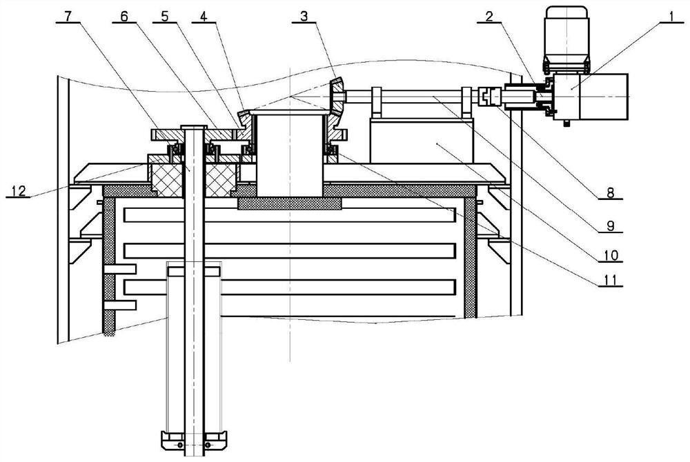
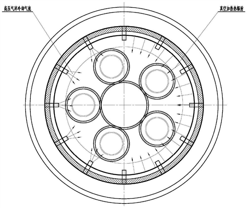
[0034] Such as figure 1 , figure 2 As shown, it includes driving gear motor 1, shaft sealing device 2, driving gear Ⅰ 3, driven gear Ⅰ 4, driving gear Ⅱ 5, driven gear Ⅱ 6, tooling and clamping device 7, coupling 8, transmission shaft 9, transmission shaft support Structure 10, driving gear II supporting structure 11, driven gear II supporting structure 12, wherein:

[0035] The drive deceleration motor is installed on the furnace shell, and the motor speed is adjustable.

[0036] The shaft sealing device is used to seal the output shaft of the driving geared motor to ensure reliable sealing of the driving system during vacuum heating and high-pressure gas quenching stages.

[0037] The driving gear I is a bevel gear, installed on the transmission shaft, and connected with the output shaft of the drive reduction motor through a coupling. The coupling can be quickly disassembled to meet the needs of loading, unloading and maintenance.

[0038] The driven gear I is a bevel gea


PUM


Abstract

The invention discloses a transmission and clamping structure capable of realizing self-rotation of a workpiece in a vacuum furnace. The structure comprises a driving gear motor, a shaft seal device, a driving gear I, a driven gear I, a driving gear II, a driven gear II, a workpiece clamping device, a coupler, a transmission shaft, all component supporting structures and the like, wherein the transmission shaft is fixed on a hearth upper cover by means of a transmission shaft supporting structure, the driving gear II and the driven gear I are of an integrated structure and are installed on the hearth upper cover by means of a driving gear II supporting structure, the workpiece clamping device and the driven gear II are fixed on the hearth upper cover by means of the driven gear II supporting structure, and the workpiece is clamped and hoisted at the lower part of the workpiece clamping device. On the premise that bidirectional sealing and thermal protection are guaranteed, the workpiece can be driven by the gear motor by means of a gear transmission system to automatically and stably rotate, and loading and unloading are facilitated; and by means of the structure, all parts of the workpiece can be evenly heated and cooled, heat treatment distortion is reduced, and the consistency of the heat treatment performance of the workpiece is improved.

Description


Claims


Application Information

Patent Timeline
Owner BEIJING RES INST OF MECHANICAL&ELECTRICAL TECH
Why Eureka
Try Eureka