Tray structure

Pending Publication Date: 2021-10-21
PLAYNITRIDE DISPLAY CO LTD
View PDF5 Cites 0 Cited by
  • Summary
  • Abstract
  • Description
  • Claims
  • Application Information

AI Technical Summary

Benefits of technology

The invention is about a tray structure that improves temperature unevenness. It uses a heat-conducting structure to increase the temperature of the central region of a second tray, which helps to even out the temperature of the substrate. This results in improved process yields.

Problems solved by technology

However, the existing tray will have uneven temperature, resulting in a situation that a central region of the substrate thereon has a lower temperature.

Method used


Image

  • Tray structure
  • Tray structure
  • Tray structure

Examples


Embodiment Construction

[0018]For ease of understanding the concept of the invention, the invention is described below with reference to embodiments and the accompanying drawings.

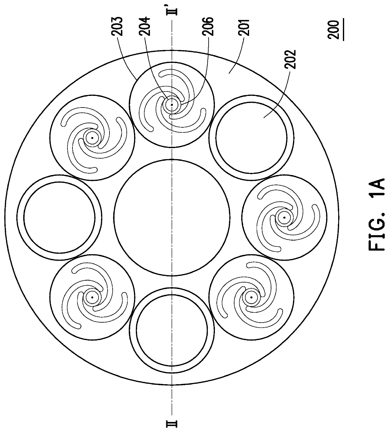
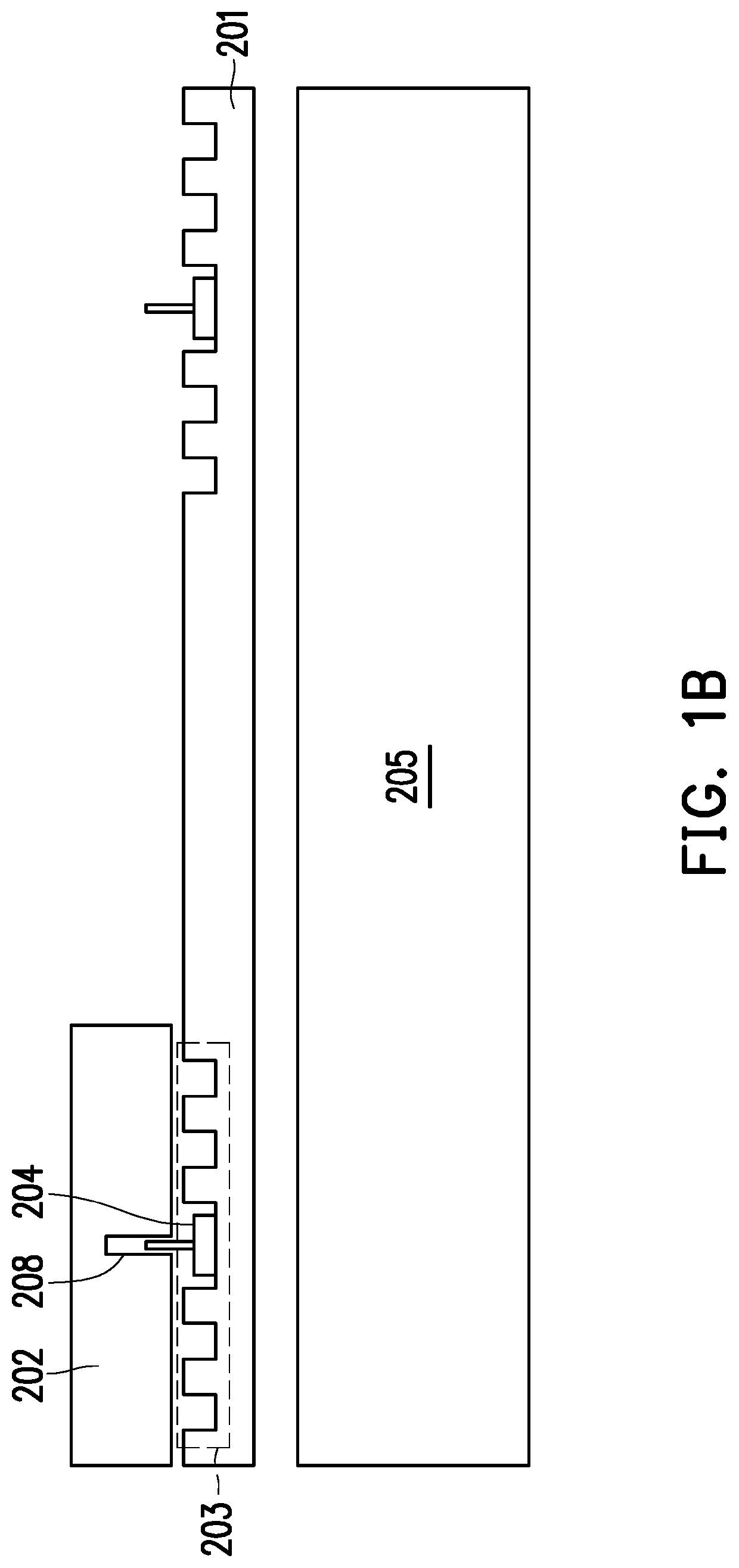
[0019]Please refer to FIGS. 1A and 1B. FIG. 1A is a tray structure according to an embodiment of the invention. FIG. 1B is a cross-sectional view taken along a dotted line II-IT when the tray structure of FIG. 1A is disposed on a deposition apparatus.

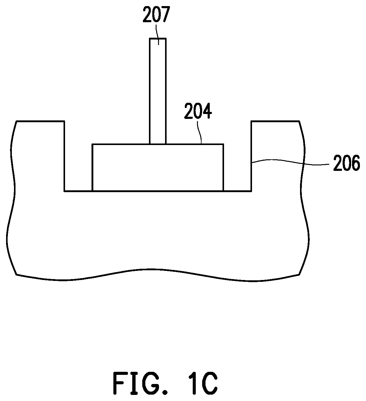
[0020]A tray structure 200 provided by the present embodiment includes a first tray 201 and a second tray 202. The first tray 201 includes a first carrying portion 203 and a heat-conducting structure 204. The first carrying portion 203 is disposed on a top surface of the first tray 201. The heat-conducting structure 204 is disposed in a recess 206 of a central region of the first carrying portion 203. The second tray 202 is disposed on the first carrying portion 203 and the heat-conducting structure 204. The tray structure 200 is adapted to be disposed on a deposition apparatus 205. T...


PUM

PropertyMeasurementUnit
Fractionaaaaaaaaaa
Fractionaaaaaaaaaa
Fractionaaaaaaaaaa

Abstract

A tray structure adapted to a deposition apparatus is provided. The tray structure includes a first tray and a second tray, wherein the first tray is disposed on the deposition apparatus for control of temperature and includes a first carrying portion and at least one heat-conducting structure. The first carrying portion is disposed on a top surface of the first tray. The at least one heat-conducting structure is disposed in a recess of the first carrying portion. The second tray is disposed on the first carrying portion and the at least one heat-conducting structure.

Description

CROSS-REFERENCE TO RELATED APPLICATION[0001]This application claims the priority benefit of Taiwan application serial no. 109113252, filed on Apr. 21, 2020. The entirety of the above-mentioned patent application is hereby incorporated by reference herein and made a part of this specification.BACKGROUND OF THE INVENTION1. Field of the Invention[0002]The invention relates to a tray structure.2. Description of Related Art[0003]An environmental condition is often an important factor that affects the epitaxy growth status of devices during semiconductor epitaxy. For example, when growing devices or layer structures on a substrate, the substrate needs to have an even temperature distribution to improve production yield.[0004]During the manufacturing process, an epitaxial tray is often used to carry an epitaxy growth substrate, and a substrate thereon is heated by a heating module of a deposition apparatus. However, the existing tray will have uneven temperature, resulting in a situation t...

Claims


Application Information

Patent Timeline
IPC IPC(8): H01L21/687C23C16/458C23C16/46C30B25/10C30B25/12
CPCH01L21/68771C23C16/4586C30B25/12C30B25/10C23C16/46H01L21/68785H01L21/67103
Inventor CHEN, CHI-HENGWU, JYUN-DELAI, YEN-LIN
Owner PLAYNITRIDE DISPLAY CO LTD
Why Eureka
Try Eureka