Novel loading limiting clutch

A clutch and load-limiting technology, which is applied in the direction of couplings, slip couplings, spring mechanisms, etc., can solve problems such as affecting the use effect, unstable state of the load limiter, complex structure of the load limiter, etc., to achieve Easy to manufacture, simple in structure and long in service life

Pending Publication Date: 2017-05-17
科美(杭州)机械有限公司
View PDF0 Cites 1 Cited by
  • Summary
  • Abstract
  • Description
  • Claims
  • Application Information

AI Technical Summary

Problems solved by technology

In the prior art, most lever hoists do not have a load limiter, and the structure of the load limiter in a few lever hoists with a load limiter is very complicated, and at the same time, the state of the load limiter is unstable, which directly affects the use effect, etc. question

Method used


Image

  • Novel loading limiting clutch

Examples


Example Embodiment

[0016] The present invention will be further described in detail with reference to the accompanying drawings and embodiments. The following embodiments are for explaining the present invention and the present invention is not limited to the following embodiments.

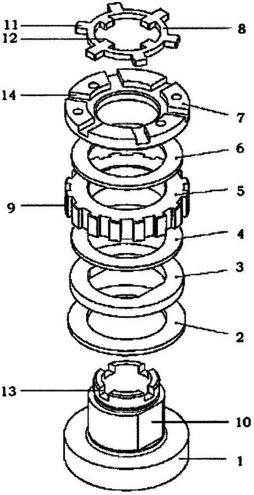
[0017] See figure 1 This embodiment includes a hub base 1, which includes an integrated disc base and a transmission shaft.

[0018] A disc spring 2, a transmission pressure plate 3, a friction plate 4, a ratchet gear 5, a friction plate 2 6 and an adjusting nut 7 are sequentially installed from the side of the transmission shaft close to the disc base. The adjusting nut 7 and the hub base 1 are connected by threads, and the relative position is kept fixed by the locking ring 8.

[0019] The outer ring of the ratchet gear 5 is provided with an integrated drive spline 9 which connects the drive wheel 5 with an external drive handle. When the worker rotates the driving handle, the driving torque can be transmitted to the ratc


PUM


Abstract

The invention relates to a novel loading limiting clutch, and belongs to the technical field of machinery. The novel loading limiting clutch comprises a hub pedestal, wherein the hub pedestal comprises an integrated disc base and a transmitting shaft; a spring, a transmission pressure plate, a first friction plate, a ratchet-gear wheel, a second friction plate and an adjusting nut are successively mounted on one side, which is close to the disc base, of the transmitting shaft; peripheral displacement limiting is carried out on space between the transmission pressure plate and the transmitting shaft; and the adjusting nut and the hub pedestal are fixed relatively through a locking ring. The adjusting nut rotates to be matched with the disc base of the hub pedestal, the friction force between assemblies can be changed, therefore, the magnitude of transmitting driving moment is changed, and the purpose of limiting loading is achieved; by the locking ring, the adjusting nut and the hub pedestal can be fixed relatively, so that stability of loading limiting moment is guaranteed; and using stability of the loading limiting clutch is guaranteed.

Description


Claims


Application Information

Patent Timeline
Owner 科美(杭州)机械有限公司
Why Eureka
Try Eureka