Energy dissipation property testing device of bolting connection part, testing method and molding method

A technology of bolted joints and energy dissipation, which is applied in the testing of machines/structural components, measuring devices, testing of mechanical components, etc., and can solve the problems of not testing the energy dissipation characteristics of bolted joints

Active Publication Date: 2017-05-31
XI'AN UNIVERSITY OF ARCHITECTURE AND TECHNOLOGY
View PDF3 Cites 4 Cited by
  • Summary
  • Abstract
  • Description
  • Claims
  • Application Information

AI Technical Summary

Benefits of technology

This new technology allows for precise measurements on bolt-jointed components without having them undergo significant changes during testing or use over time due to their unique properties such as temperature variation.

Problems solved by technology

This patents describes how different types of materials can have an impact upon the behavior or function of structures made up from these components. It explains why this problem arises because current techniques involve complex calculations involving multiple variables like stress levels in the component's construction process, temperature conditions during manufacturing processes, etc., which cannot easily predict accurately any changes caused by external forces. Therefore, technical solutions aimed at simplifying the calculation involved should also provide accurate results through simulations with realistic environmental effects.

Method used


Image

  • Energy dissipation property testing device of bolting connection part, testing method and molding method
  • Energy dissipation property testing device of bolting connection part, testing method and molding method
  • Energy dissipation property testing device of bolting connection part, testing method and molding method

Examples


Embodiment Construction

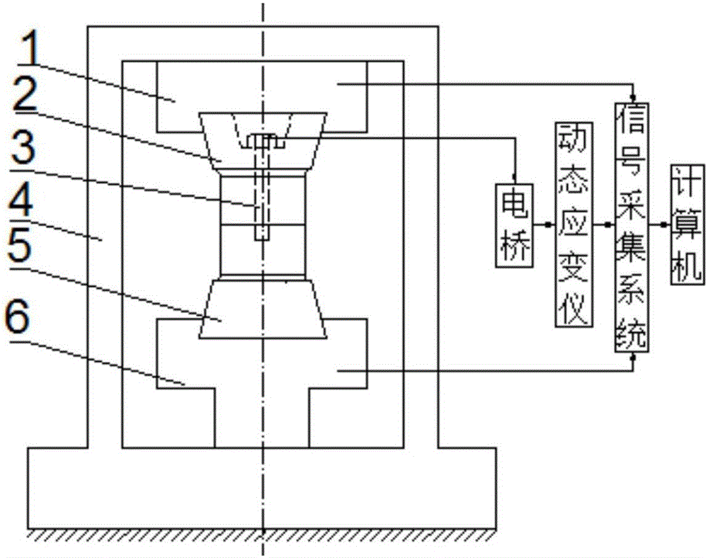
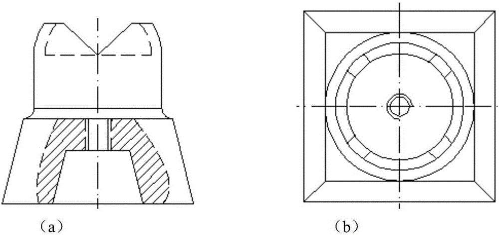
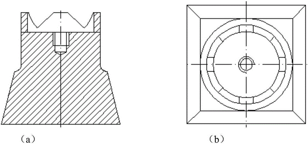
[0071] The device for testing bolt energy dissipation characteristics of the present invention will be further described in detail below in conjunction with the working principle and the structural drawings. Such as Figure 1 to Figure 4 Shown in (b), a kind of test device of the energy dissipation characteristic of the bolt joint of the present invention comprises a force tensile testing machine 4, an upper test piece 2, a lower test piece 5, a high-strength bolt 3, a strain gauge, an electric bridge , dynamic strain gauge, signal acquisition system and computer. Utilize a torque wrench to fix the upper fixture 1 of the upper specimen 2 and the tensile testing machine 4, and fix the lower specimen 5 and the lower clamp 6 of the tensile testing machine 4; In order to ensure the coaxiality, first clamp the lower test piece 5, and after adjusting the upper clamp 1 of the tensile testing machine 4, clamp the upper test piece 2; extend the center of the screw axis of the high-streng


PUM


Abstract

The invention discloses an energy dissipation property testing device of a bolting connection part, a testing method and a molding method; the testing device comprises a force tensile testing machine, an upper test piece, a lower test piece, a bolt, a strain gage, a bridge, a dynamic strain meter, a signal collecting system and a computer; the upper test piece is fixed with an upper clamp of the force tensile testing machine, and the lower test piece is fixed with a lower clamp of the force tensile testing machine; the upper test piece and the lower test piece are fixed through the bolt; the strain gage is placed in the bolt, and connected with the bridge; the bridge is connected with the signal collecting system through the dynamic strain meter; the force and displacement of the force tensile testing machine are sent to the signal collecting system through the force sensor and the displacement sensor respectively; the signal collecting system is connected with the computer and sends the testing data of the collected bolting combining part force, displacement and bolt pre-tightening force to the computer. The device is simple in structure, convenient to mount and dismount, and easy to repeat test, and solves the problem that the lagged non-linear property of the bolting combining part is hard to test.

Description


Claims


Application Information

Patent Timeline
Owner XI'AN UNIVERSITY OF ARCHITECTURE AND TECHNOLOGY
Why Eureka
Try Eureka