Method for drying ceramic green body in drying chamber

A ceramic green body and drying method technology, applied in the field of ceramic production, can solve the problems of high cracking rate and long time consumption of the green body, and achieve the effects of reducing the process, increasing the cracking rate, and increasing the drying speed

Inactive Publication Date: 2017-06-20
LIXIL AS SANITARY MFG (SHANGHAI) CO LTD
View PDF6 Cites 6 Cited by
  • Summary
  • Abstract
  • Description
  • Claims
  • Application Information

AI Technical Summary

Problems solved by technology

It can be seen that the drying method of the existing ceramic green body has the defects of long time consumption and high cracking rate of the green body

Method used


Image

  • Method for drying ceramic green body in drying chamber
  • Method for drying ceramic green body in drying chamber
  • Method for drying ceramic green body in drying chamber

Examples


Example Embodiment

[0026] A preferred embodiment is given below to illustrate the present invention more clearly and completely in conjunction with the accompanying drawings.

[0027] A method for drying a ceramic body in a drying oven, which includes the following steps:

[0028] Step 1. Place the ceramic body in the drying room.

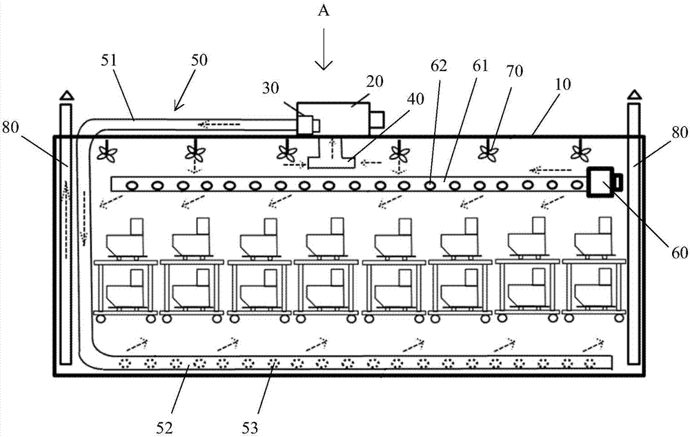
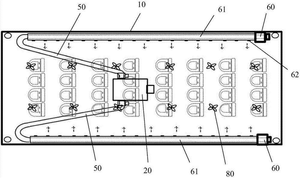
[0029] Such as figure 1 with figure 2 As shown, the drying room includes a room body 10, and a hot air generating system 20 is provided on the outside of the room body 10. The hot air generation system 20 includes a circulating fan 30 and an air inlet 40, and the air inlet 40 is located at the top of the inner cavity of the house 10.

[0030] The circulating fan 30 is connected with two circulating air ducts 50. Each circulating air pipe 50 includes an air supply pipe section 51 connected to the circulating fan 30 and an air outlet pipe section 52 connected to the air supply pipe section 51. The air outlet pipe section 52 is provided with a plurality of circulating air outlet


PUM


Abstract

The invention discloses a method for drying a ceramic green body in a drying chamber. The method includes the following steps that the ceramic green body is placed into the drying chamber, drying time at the first stage is 25-35 minutes, the temperature is 34-36 DEG C, and the humidity is 91%-93%RH; drying time at the second stage is 950-970 minutes, the temperature is 39-41 DEG C, and the humidity is 91%-93%RH; drying time at the third stage is 770-790 minutes, the temperature is 44-46 DEG C, and the humidity is 83%-87%RH; drying time at the fourth stage is 530-550 minutes, the temperature is 69-71 DEG C, and the humidity is 9%-11%RH; drying time at the fifth stage is 500-520 minutes, the temperature is 69-71 DEG C, and the humidity is 9%-11%RH; and cooling time at the sixth stage is 25-35 minutes, the temperature is 9-11 DEG C, and the humidity is 9%-11%RH. The drying method has the advantages of being short in time consumption and low in cracking rate of ceramic green bodies.

Description


Claims


Application Information

Patent Timeline
Owner LIXIL AS SANITARY MFG (SHANGHAI) CO LTD
Why Eureka
Try Eureka