Transformer and switch power supply

A switching power supply and transformer technology, applied in the direction of transformer/inductor magnetic core, circuit, electrical components, etc., can solve the problem of increasing the height of the transformer, achieve the effect of reducing the overall thickness and saving space in the thickness direction

Active Publication Date: 2017-07-07
HUAWEI DIGITAL POWER TECH CO LTD
View PDF7 Cites 0 Cited by
  • Summary
  • Abstract
  • Description
  • Claims
  • Application Information

AI Technical Summary

Benefits of technology

This patented design allows for better performance by reducing the size of an electric device's main component (power transformers). It achieves this through separating certain components from each others within its own structure or placing them at different locations inside it itself instead of being placed next to eachother. By doing that we can save more room than traditional designs with multiple layers of insulation between conductors.

Problems solved by technology

This patented describes how it can make switches that use less space while still providing their necessary performance for them. However, there may also happen when adding or removing certain parts from these devices due to changes made during manufacturing processes such as temperature variations over time (T). These modifications affects the size and weight of the device itself.

Method used


Image

  • Transformer and switch power supply
  • Transformer and switch power supply
  • Transformer and switch power supply

Examples


Embodiment Construction

[0022] Embodiments of the present invention will be described below with reference to the drawings in the embodiments of the present invention.

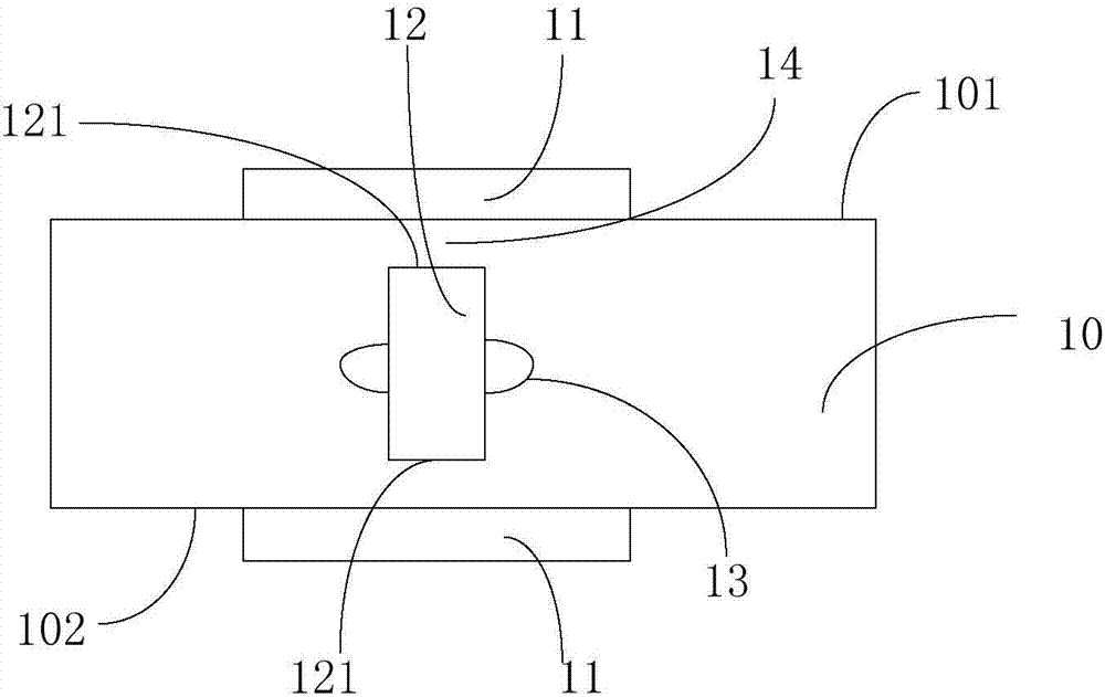
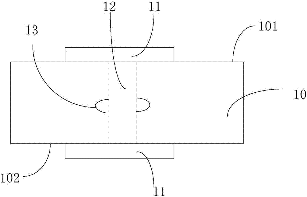
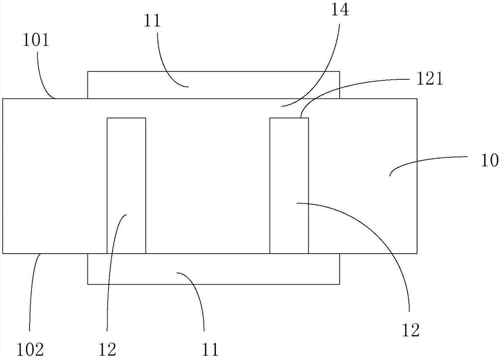
[0023] The transformer provided by the embodiment of the present invention is used for switching power supply or AC power supply. See figure 1 , the transformer in this embodiment is used as a switching power supply transformer as an example. The transformer includes a circuit board 10, two first magnetic core bodies 11 and at least one second magnetic core body 12 (attached figure 1 Take one as an example), the circuit board 10 includes two opposite surfaces 101 and 102 . The at least one second magnetic core body 12 is embedded in the circuit board 10 along the thickness direction of the circuit board 10, and the two first magnetic core bodies 11 are respectively fixed on the two opposite surfaces 101 and the surface 102, the at least one second magnetic core body 12 is located between the two first magnetic core bodies 11, and the


PUM


Abstract

The invention discloses a transformer. The transformer comprises a circuit board, two first magnetic core bodies and at least one second magnetic core body, wherein the circuit board has two opposite surfaces; the at least one second magnetic core body is embedded into the circuit board along the thickness direction of the circuit board; the two first magnetic core bodies are respectively fixed on the two opposite surfaces; the at least one second magnetic core body is positioned between two first magnetic core bodies; and the two first magnetic core bodies and the at least one second magnetic core body form a magnetic core of the transformer. The invention also provides a switch power supply.

Description


Claims


Application Information

Patent Timeline
Owner HUAWEI DIGITAL POWER TECH CO LTD
Why Eureka
Try Eureka