Automatic lifting protective guard used at highway-railway intersection

A technology of automatic lifting and railway entrance, applied in the direction of the manipulation of highway barriers, etc., can solve the problems of increased railway construction costs, unsuitable road barriers, and high cost maintenance costs, so as to reduce construction costs, avoid railway construction costs, and avoid manpower. The effect of wasting resources

Inactive Publication Date: 2017-07-18
广西云厦建设有限公司
View PDF5 Cites 4 Cited by
  • Summary
  • Abstract
  • Description
  • Claims
  • Application Information

AI Technical Summary

Benefits of technology

This technology helps prevent trains from entering wrong areas during rush hours without requiring safety barriers or other physical features like gates. When there are no traffic signals for it's safe route, they automatically adjust their height accordingly based upon factors such as speed limits along its way. They then move backward under these conditions until reaching certain points where signal lights indicate them again. These technical improvements help maintain better efficiency while reducing costs compared to previous methods.

Problems solved by technology

The technical problem addressed in this patented text relates to prevention of safety hazards caused from overlapping traffic or collisions with other objects along different types of rails within a railway track network. Current methods involve manually controlling protection barriers around corners where intersect lines may exist, which requires significant labor costs and makes them difficult to maintain properly throughout their lifetime. Therefore, we propose developing an automated lift system called Automatic Lifelines (ALS) for better efficiency and reliability across various sections of railway tracks.

Method used


Image

  • Automatic lifting protective guard used at highway-railway intersection
  • Automatic lifting protective guard used at highway-railway intersection
  • Automatic lifting protective guard used at highway-railway intersection

Examples


Embodiment Construction

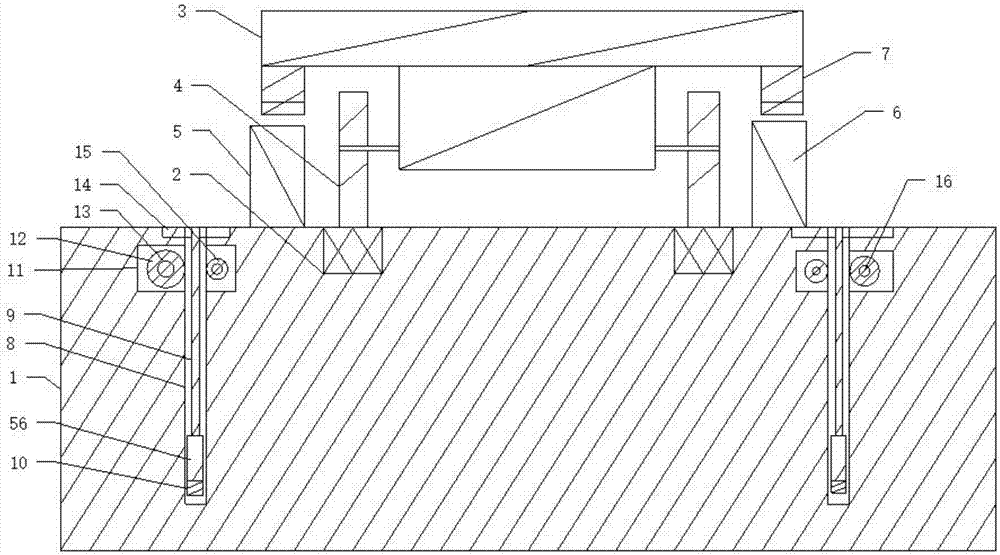
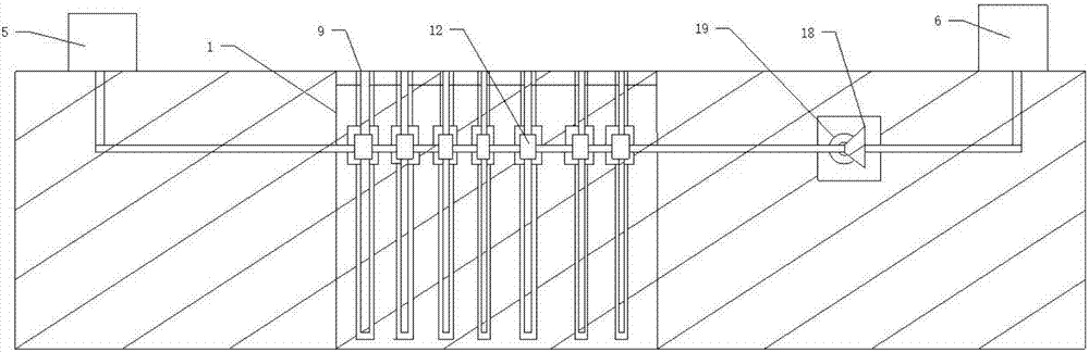
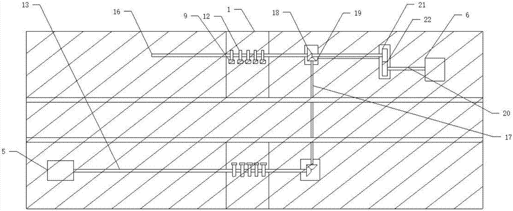
[0033] Such as Figure 1 to Figure 11 Shown, a kind of highway railroad crossing automatic lifting guardrail, comprises subgrade 1, and described subgrade 1 is provided with two corresponding tracks 2, and described track 2 is provided with a train 3, and described train 3 is provided with The wheels 4 rotating on the track 2, the two sides of the track 2 respectively include a row of first sliding holes 8 arranged on the roadbed 1, and a sliding protective railing 9 is respectively arranged in the first sliding holes 8 The two sides of the track 2 are respectively provided with a first inner chamber 11 correspondingly connected with the first slide holes 8 side by side, and the two sides of the track 2 are respectively provided with a First rotating shaft 13 and a second rotating shaft 16, described first rotating shaft 13 and described second rotating shaft 16 are respectively provided with a drive gear 12 that drives described protective railing 9 to slide, described protectiv


PUM


Abstract

The invention discloses an automatic lifting protective guard used at a highway-railway intersection. A row of first sliding holes formed in a roadbed is formed in each of the two sides of the rails; a sliding protective guard bar is arranged inside each first sliding hole; a first rotating shaft and a second rotating shaft which rotate inside first inner cavities are arranged on the two sides of the rails respectively; driving gears driving the protective guard bars to slide are arranged on the first rotating shaft and the second rotating shaft respectively; the protective guard bars on the two sides correspond to a train; a control sliding plate is arranged on each of the two sides of the train; a first magnetic disc is arranged on each control sliding plate; a second magnetic disc correspondingly magnetically attracting the first magnetic disc is arranged each sliding top pressure plate. The lifting of the protective guard bars can further be controlled through driving of the train, so that railway construction cost increase caused by manual control over the lifting of the protective guard bars is further avoided.

Description


Claims


Application Information

Patent Timeline
Owner 广西云厦建设有限公司
Why Eureka
Try Eureka