Composite welding method of pillow beam, pillow beam and rail vehicle with pillow beam

A hybrid welding and composite welding technology, applied in the field of rail vehicles, to achieve the effects of improving corrosion resistance, good gap adaptability, and improving manufacturing and processing efficiency

Inactive Publication Date: 2017-07-21
CRRC QINGDAO SIFANG CO LTD
View PDF6 Cites 17 Cited by
  • Summary
  • Abstract
  • Description
  • Claims
  • Application Information

AI Technical Summary

Benefits of technology

This patented technology allows for better design of an aluminum railway vehicle's roof panel with improved strength without adding extra weight compared to traditional methods like galvanized steal or other materials such as chrome sheetings. It also includes optimizing the placement of rib elements within the assembly, which results in lighter structures while maintaining their effectiveness at high temperatures. Additionally, it uses self constraint techniques to ensure stable connections between different parts during use over time. Overall this makes these new ways to make stronger metal components more efficient than older options.

Problems solved by technology

This patented technical problem addressed in this patents relates to replacing conventional metal reinforcements like iron or aluminum alloys in railway cars without compromising their weight-to-strength ratio. Existing solutions involve adding thicker metals instead of thin plates, increasing production cost while reducing mechanical properties. Additionally, there may exist concerns over potential issues caused during welded joints through environmental factors including temperature fluctuations and vibrational waves.

Method used


Image

  • Composite welding method of pillow beam, pillow beam and rail vehicle with pillow beam
  • Composite welding method of pillow beam, pillow beam and rail vehicle with pillow beam
  • Composite welding method of pillow beam, pillow beam and rail vehicle with pillow beam

Examples


Embodiment 1

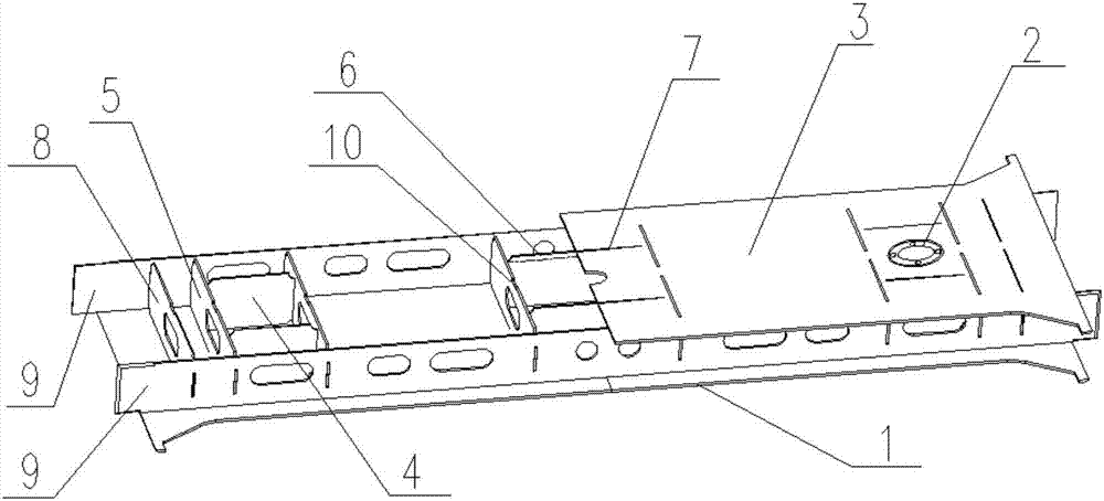
[0043] Embodiment 1 proposes a corbel, such as figure 1 As shown, the corbel adopts austenitic stainless steel material SUS301L instead of weathering steel material, which realizes the lightweight of corbel and improves the corrosion resistance of corbel. The corbel includes a lower cover 3, an upper cover 1, and two side webs 9 connected between the upper cover 1 and the lower cover 3, and the two side webs 9 are respectively connected with the upper cover 1 and the lower cover The plate 3 is arranged vertically, and the lower cover plate 3, the web plates 9 on both sides and the upper cover plate 1 are welded to form a hollow box-shaped structure. The box-shaped structure is welded with ribs, which are composed of a plurality of ribs in advance. It is assembled and welded, and the assembled rib plate is formed with a plurality of plug joints 6 extending outward for subsequent plug-in operations. figure 1 In order to facilitate the display of the internal structure of the box-s

Embodiment 2

[0058] The second embodiment proposes a composite welding method for the corbel, which can be used to weld and manufacture the corbel as described in the first embodiment, so that the corbel can be made of stainless steel as a whole instead of the weathering steel material, so that the weight of the corbel can be reduced, Improve the corrosion resistance of the corbel, and have the process effect of single-sided welding and double-sided forming, which can reduce the welding deformation, solve the problem of serious residual stress, effectively improve the welding quality, and realize the maintenance-free manufacturing process of the stainless steel corbel.

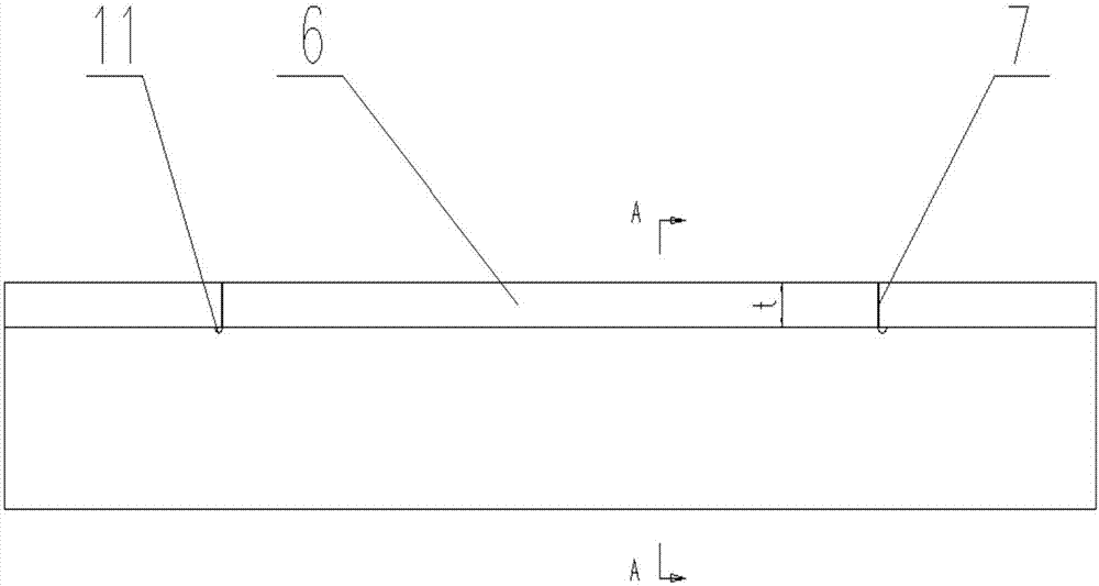
[0059] like Figure 7 As shown, the method includes the following steps:

[0060] S1. Pre-assemble and weld a plurality of rib plates to form a rib plate composition, and the rib plate composition has a plurality of plug connectors 6 extending outward;

[0061] S2. Insert the lower cover 3, the two side webs 9 connected betw

Embodiment 3

[0083] On the basis of the method described in the second embodiment, the third embodiment provides a more complete example of welding processing of corbels, so as to further improve the method described in the second embodiment in detail.

[0084] In the method described in the third embodiment, according to the processing principle of first assembly and then parts, formulating the manufacturing process flow of the bolster includes in sequence: pre-assembly of the rib plate assembly, welding of the bolster, processing of the bolster, welding of the seat plate, and There are five steps in seat plate processing.

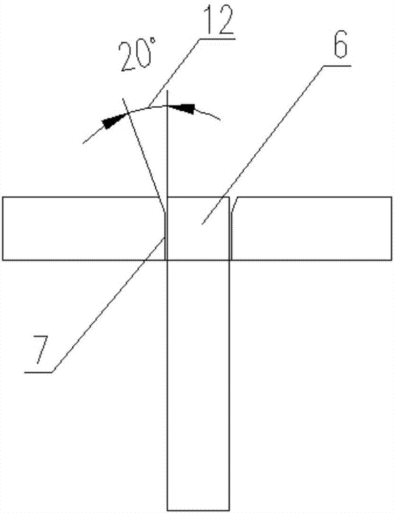
[0085] Step (1) Pre-assembly of the rib plate assembly: Use a master to connect the two ends of a pair of transverse rib plates 4 between a pair of longitudinal rib plates 5 respectively, so as to pre-assemble a rectangular structure, and then perform laser- MAG composite welding; wherein, on the basis of the length dimension of the transverse rib plate 4, a process weig


PUM


Abstract

The invention relates to the field of rail transportation and machinery manufacturing, and particularly to a composite welding method of a pillow beam, the pillow beam and a rail vehicle with the pillow beam. The method comprises the following steps that laser-MAG composite welding is used for welding the pillow beam of the stainless steel material, and inserted-connected structures of rib plates are optimized; during manufacturing, the rib plates are preassembled and welded to form a rib plate assembly, then the whole structure is welded, so that the pillow beam can adopt to the stainless steel material to replace weathering resistant steel material in whole, the lightweightening of the pillow beam is achieved, and the corrosion resistance of the pillow beam is improved; through the welding modes of inserting connection and corner connection, and a to-be-welded welding seam is placed on the outer surface of a box type structure to adapt to a technology of single-face welding double-face forming of the laser-MAG composite welding; and self-restraint of pillow beam welding is achieved through the self-stiffness of the inserted-connected structures, the advantages of the laser-MAG composite welding of deep welding, low heat input, small welding deformation and good gap adaptability are played, a manufacturing technology without adjustment and repair of the stainless steel pillow beam is achieved, so that the manufacturing and processing efficiency of the rail vehicle are improved, and production cost is reduced.

Description


Claims


Application Information

Patent Timeline
Owner CRRC QINGDAO SIFANG CO LTD
Why Eureka
Try Eureka