Automatic sole rubber cutting device
A cutting device and rubber technology, applied in footwear, heel pads, shoe-making machinery, etc., can solve the problems of high risk and loss of manual cutting
- Summary
- Abstract
- Description
- Claims
- Application Information
AI Technical Summary
Problems solved by technology
Method used
Image

Examples
Embodiment 1
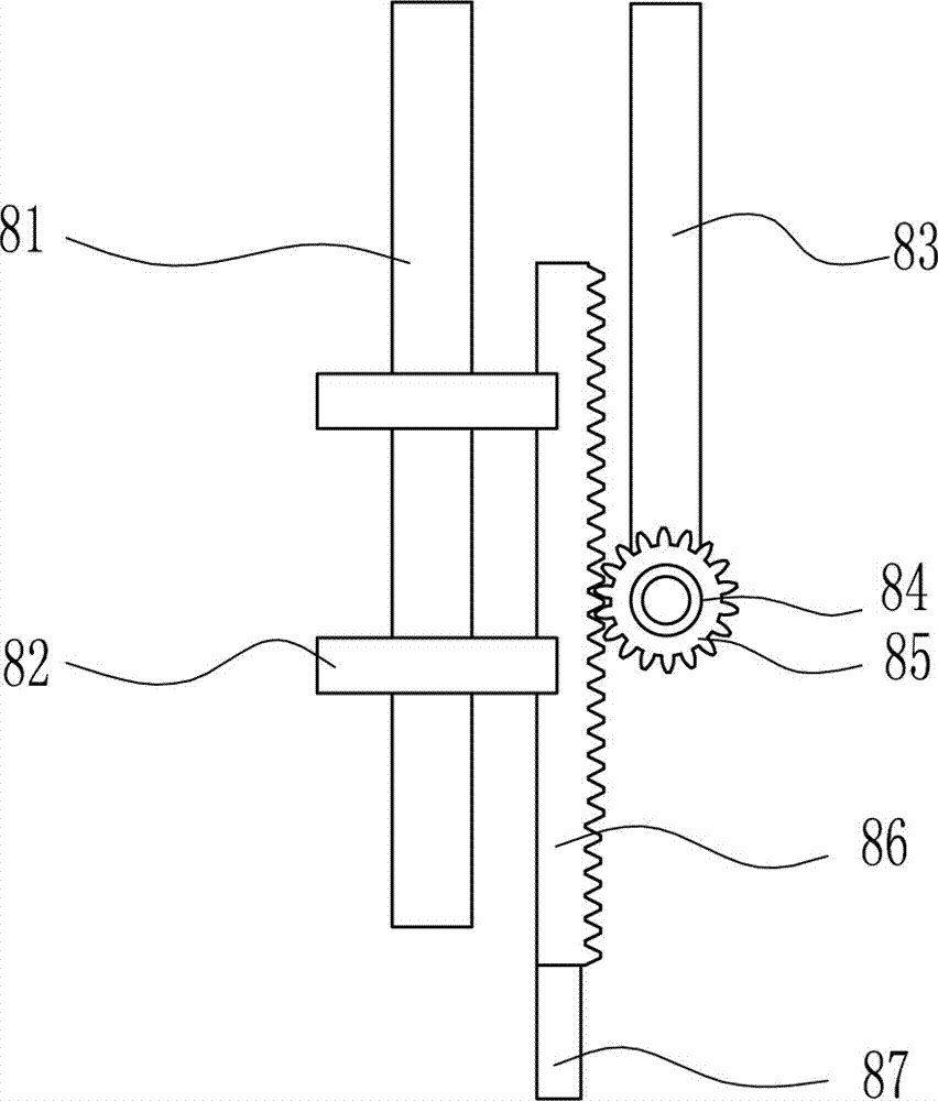
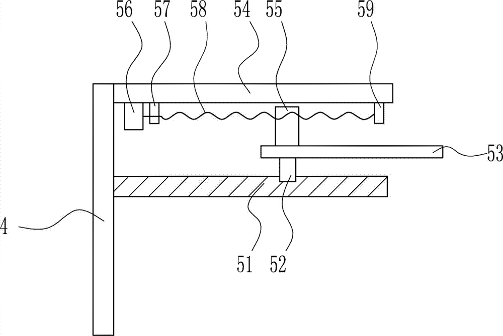
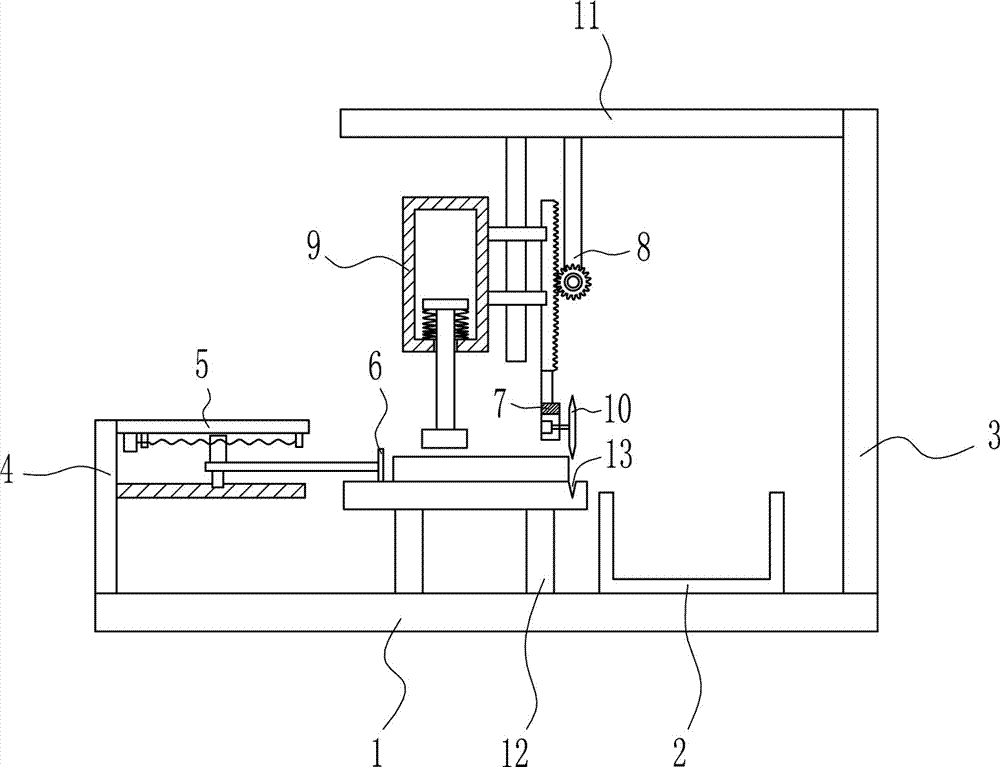
[0035] A sole rubber automatic cutting device, such as Figure 1-6 As shown, it includes a base plate 1, a collection frame 2, a first pole 3, a second pole 4, a pushing mechanism 5, a push plate 6, a front and rear moving mechanism 7, a lifting mechanism 8, a pressing mechanism 9, a cutting mechanism 10, The top plate 11 and the wooden table 12, the first pole 3 and the second pole 4 are fixed on both ends of the bottom plate 1 along the straight line, the collection frame 2 and the wooden table 12 are placed on the bottom plate 1, and the top plate 11 is fixed on the first support On the top of the rod 3, the pushing mechanism 5 is fixedly connected to one side of the second support rod 4, and the push plate 6 is connected to the output end of the pushing mechanism 5; Transmission connection, the front and rear moving mechanism 7 is connected to the output end of the lifting mechanism 8, the lifting mechanism 8 is used to drive the front and rear moving mechanism 7 and the p...
Embodiment 2
[0037] A sole rubber automatic cutting device, such as Figure 1-6 As shown, it includes a base plate 1, a collection frame 2, a first pole 3, a second pole 4, a pushing mechanism 5, a push plate 6, a front and rear moving mechanism 7, a lifting mechanism 8, a pressing mechanism 9, a cutting mechanism 10, The top plate 11 and the wooden table 12, the first pole 3 and the second pole 4 are fixed on both ends of the bottom plate 1 along the straight line, the collection frame 2 and the wooden table 12 are placed on the bottom plate 1, and the top plate 11 is fixed on the first support On the top of the rod 3, the pushing mechanism 5 is fixedly connected to one side of the second support rod 4, and the push plate 6 is connected to the output end of the pushing mechanism 5; Transmission connection, the front and rear moving mechanism 7 is connected to the output end of the lifting mechanism 8, the lifting mechanism 8 is used to drive the front and rear moving mechanism 7 and the p...
Embodiment 3
[0040] A sole rubber automatic cutting device, such as Figure 1-6 As shown, it includes a base plate 1, a collection frame 2, a first pole 3, a second pole 4, a pushing mechanism 5, a push plate 6, a front and rear moving mechanism 7, a lifting mechanism 8, a pressing mechanism 9, a cutting mechanism 10, The top plate 11 and the wooden table 12, the first pole 3 and the second pole 4 are fixed on both ends of the bottom plate 1 along the straight line, the collection frame 2 and the wooden table 12 are placed on the bottom plate 1, and the top plate 11 is fixed on the first support On the top of the rod 3, the pushing mechanism 5 is fixedly connected to one side of the second support rod 4, and the push plate 6 is connected to the output end of the pushing mechanism 5; Transmission connection, the front and rear moving mechanism 7 is connected to the output end of the lifting mechanism 8, the lifting mechanism 8 is used to drive the front and rear moving mechanism 7 and the p...
PUM
 Abstract
Description
Claims
Application Information
 - R&D Engineer
- R&D Manager
- IP Professional
- Industry Leading Data Capabilities
- Powerful AI technology
- Patent DNA Extraction
Browse by: Latest US Patents, China's latest patents, Technical Efficacy Thesaurus, Application Domain, Technology Topic.
© 2024 PatSnap. All rights reserved.Legal|Privacy policy|Modern Slavery Act Transparency Statement|Sitemap