High-performance axial-flow fan for extractor hood

A technology of range hoods and axial flow fans, which is applied to parts of pumping devices for elastic fluids, machines/engines, mechanical equipment, etc., and can solve problems such as wind resistance of wind rotors, influence of wind rotor speed, and reduction of wind pressure , to achieve the effect of improving separation, improving fluid power efficiency and reducing motion wind resistance

Pending Publication Date: 2018-03-02
胡俊铨
View PDF0 Cites 1 Cited by
  • Summary
  • Abstract
  • Description
  • Claims
  • Application Information

AI Technical Summary

Problems solved by technology

In order to improve the separation degree of grease in the oil fume, it is necessary to increase the fan speed to generate high wind pressure. At present, the fan of the range hood generally adopts a planar wind wheel structure, and the inner wall of the fan and the wind direction generated by the rotation of the wind wheel are perpendicular

Method used


Image

  • High-performance axial-flow fan for extractor hood
  • High-performance axial-flow fan for extractor hood
  • High-performance axial-flow fan for extractor hood

Examples


Embodiment Construction

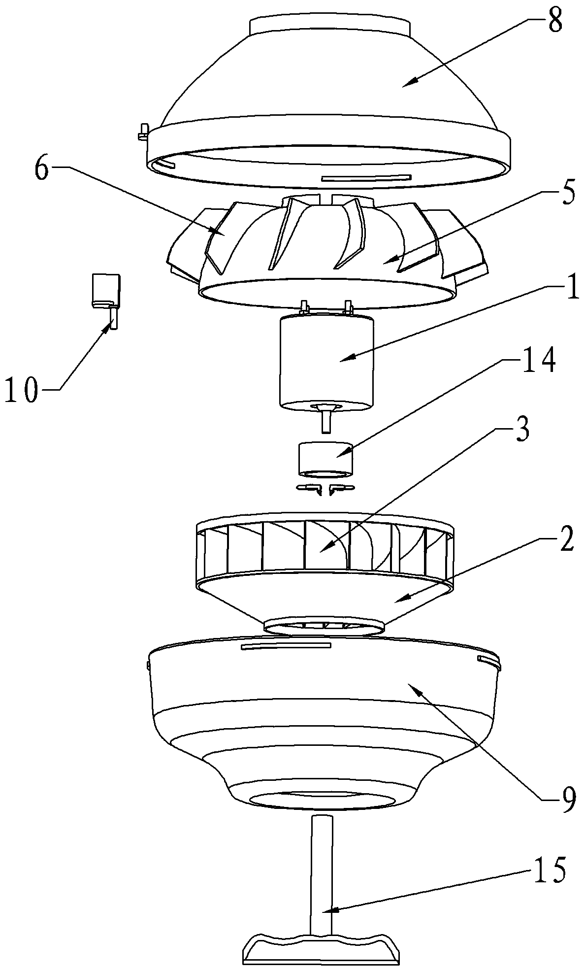
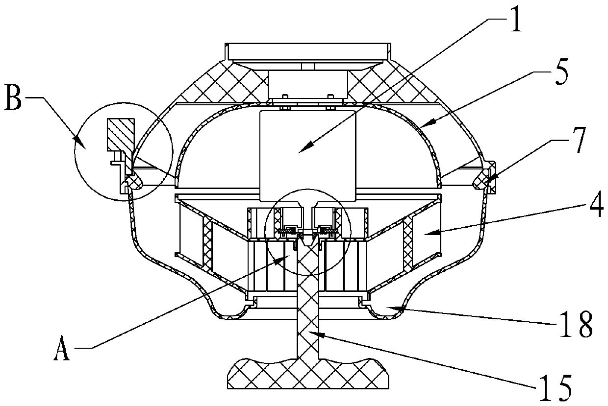
[0019] Such as figure 1 and figure 2 As shown, a high-performance axial flow fan for a range hood includes a casing and a centrifugal wind wheel 2 installed in the casing and driven by a motor 1. The centrifugal wind wheel 2 is at least composed of radially distributed arc-shaped blades 3, adjacent to An air channel 4 is formed between the arc-shaped blades 3, and the air channel 4 is inclined toward the air outlet of the fan along the direction from inside to outside. The inclined air duct 4 is designed so that the high-pressure wind generated by the centrifugal wind wheel 2 rebounds to the exhaust outlet of the fan after hitting the inner wall of the casing, and will not enter the centrifugal fan again. This design can greatly reduce the wind of the centrifugal wind wheel 2. The turbulence between the outlet of channel 4 and the inner wall of the shell improves the overall fluid dynamic efficiency of the fan, thereby reducing the movement wind resistance of the centrifugal fa


PUM


Abstract

The invention provides a high-performance axial flow fan for range hoods, which includes a casing and a centrifugal wind wheel installed in the casing and driven by a motor. The centrifugal wind wheel is at least composed of radially distributed arc-shaped blades, adjacent An air duct is formed between the arc-shaped blades, and the air duct is inclined toward the air outlet of the fan along the direction from inside to outside. The inclined air duct design makes the high-pressure wind generated by the centrifugal fan rebound to the exhaust outlet of the fan after hitting the inner wall of the casing, and will not enter the centrifugal fan again. The turbulence between the inner walls of the casing improves the overall fluid dynamic efficiency of the fan, thereby reducing the movement wind resistance of the centrifugal fan, enabling the centrifugal fan to rotate at high speed and generate high-pressure air above 600Pa, so that the grease in the oil fume can condense into small oil Drops, improving the separation of oil and fat.

Description


Claims


Application Information

Patent Timeline
Owner 胡俊铨
Why Eureka
Try Eureka