Industrial automatic crusher

An industrial automation and pulverizer technology, applied in the field of industrial production, can solve the problems of reducing production efficiency and inconvenient continuous operation, and achieve the effect of improving production efficiency and protecting the production environment.

Inactive Publication Date: 2018-03-06
CHENGDU HONGYUE TECH CO LTD
View PDF0 Cites 0 Cited by
  • Summary
  • Abstract
  • Description
  • Claims
  • Application Information

AI Technical Summary

Problems solved by technology

The existing pulverizer needs to separate the powder from the large particles after pulverizati

Method used


Image

  • Industrial automatic crusher
  • Industrial automatic crusher

Examples


Embodiment Construction

[0017] The following will clearly and completely describe the technical solutions in the embodiments of the present invention with reference to the accompanying drawings in the embodiments of the present invention. Obviously, the described embodiments are only some, not all, embodiments of the present invention.

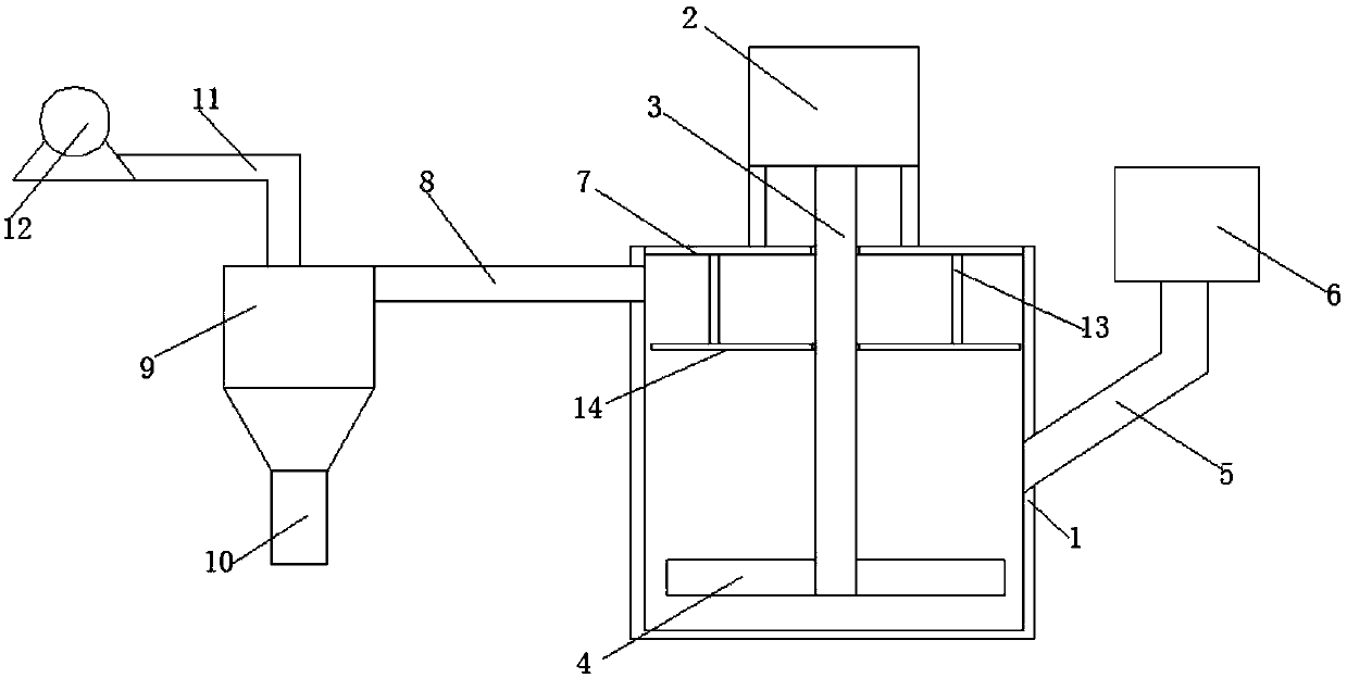
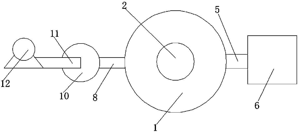
[0018] refer to Figure 1-2 , an industrial automatic pulverizer, including a box body 1, a cover plate 7 is installed on the upper end of the box body 1 through a card slot, a motor 2 is installed on the upper end of the cover plate 7 through a support rod, and the output end of the motor 2 is connected to the The rotating shafts 3 are connected, the lower end of the rotating shaft 3 is welded with a blade 4, and the lower end of the cover plate 7 is welded with a bracket 13, the lower end of the bracket 13 is equipped with a filter screen 14 through screws, and the upper end of the side wall of the box body 1 is welded with a discharge Pipe 8, the other end of the dis


PUM


Abstract

The invention discloses an industrial automatic pulverizer, which comprises a box body, a cover plate is installed on the upper end of the box body through a card slot, a motor is installed on the upper end of the cover plate through a support rod, and the output end of the motor is connected to the rotating shaft through a coupling. The lower end of the rotating shaft is welded with a blade, the lower end of the cover plate is welded with a bracket, the lower end of the bracket is installed with a filter screen through screws, the upper end of the side wall of the box is welded with a discharge pipe, and the other end of the discharge pipe is connected to the The cyclone separator is connected to each other, the lower end of the cyclone separator is provided with a discharge port, and the outlet end of the cyclone separator is connected to the induced draft fan through a draft pipe, and the middle part of the side wall of the box is welded with a feed pipe, and the feed pipe The upper end is welded to the hopper. During the use of this device, materials can be fed through the hopper. After the material is crushed by the blades, the fine materials are attracted by the induced draft fan, and finally separated by the cyclone separator. The whole operation can be operated continuously, which can improve production efficiency.

Description


Claims


Application Information

Patent Timeline
Owner CHENGDU HONGYUE TECH CO LTD
Why Eureka
Try Eureka