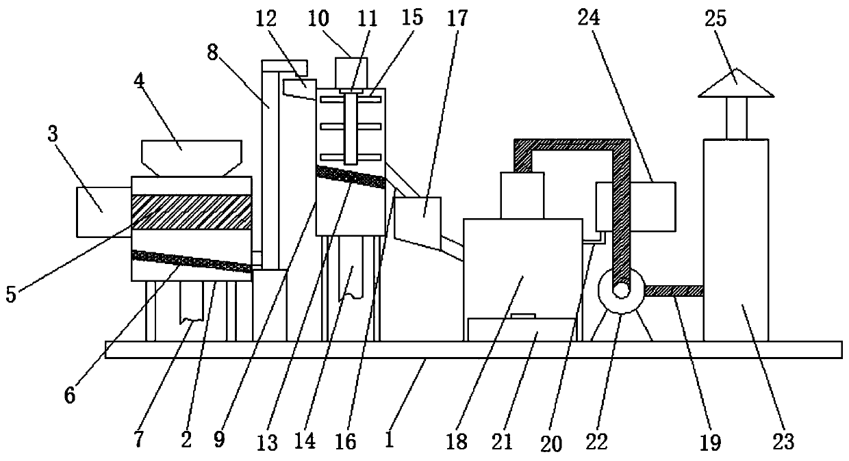
Incineration boiler used for waste power generation

A waste-to-energy and boiler technology, applied in the direction of incinerators, combustion methods, combustion types, etc., can solve the problems of increasing the consumption cost of waste energy, increasing the labor intensity of operators, weakening the convenience of incineration boilers, etc., and reducing energy consumption , Improve convenience and save cost

Inactive Publication Date: 2019-08-16
光大环保能源(沛县)有限公司
View PDF6 Cites 0 Cited by
  • Summary
  • Abstract
  • Description
  • Claims
  • Application Information

AI Technical Summary

Problems solved by technology

[0002] At present, the existing waste-to-energy incineration boilers still have some deficiencies. For example, the existing waste-to-energy incineration boilers do not crush the waste during use, which slows down the speed of waste incineration and reduces the efficiency of waste-to-energy. Efficiency, can not allow the waste water mixed in the garbage to be removed, which increases the energy consumpti

Method used


Image

  • Incineration boiler used for waste power generation

Examples


Embodiment Construction

[0019] The following will clearly and completely describe the technical solutions in the embodiments of the present invention with reference to the accompanying drawings in the embodiments of the present invention. Obviously, the described embodiments are only some, not all, embodiments of the present invention.

[0020] In describing the present invention, it should be understood that the terms "upper", "lower", "front", "rear", "left", "right", "top", "bottom", "inner", " The orientation or positional relationship indicated by "outside", etc. is based on the orientation or positional relationship shown in the drawings, and is only for the convenience of describing the present invention and simplifying the description, rather than indicating or implying that the referred device or element must have a specific orientation, so as to Specific orientation configurations and operations, therefore, are not to be construed as limitations on the invention.

[0021] see figure 1 , the p


PUM


Abstract

The invention discloses an incineration boiler used for waste power generation. The incineration boiler used for waste power generation structurally comprises a fixed base. A crushing machine is arranged at the left end of the fixed base. A driving motor, a feed inlet, a crushing roller, a first leaking plate and a first blow-off pipe are arranged on the crushing machine. The driving motor is fixedly connected to the upper left portion of the crushing machine. The feed inlet is fixedly connected to the upper end of the crushing machine. The crushing roller is movably connected into the crushing machine. The first leaking plate is fixedly connected to the lower portion of the interior of the crushing machine. The first blow-off pipe is fixedly connected to the bottom of the crushing machine. A conveying mechanism is arranged on the right side of the crushing machine. A mixing mechanism is arranged on the right side of the conveying mechanism. By adoption of the incineration boiler usedfor waste power generation, waste can be crushed, the waste incineration speed is increased, the waste power generation efficiency is improved, energy consumption during waste incineration is reduced,and the waste incineration cost is reduced.

Description


Claims


Application Information

Patent Timeline
Owner 光大环保能源(沛县)有限公司
Why Eureka
Try Eureka