Oiling device for winding machine

A technology of winding machine and oil supply device, which is used in transportation and packaging, transportation of filamentous materials, and thin material processing, etc., can solve the problems of excessive oil pollution of products, polluted machines, and splashing of line oil, etc., and achieves a feasible solution. The effect of saving usage and reducing flower and hair pollution

Inactive Publication Date: 2018-03-16
WUJIANG HONGRUI PRECISION MASCH FACTORY
View PDF0 Cites 0 Cited by
  • Summary
  • Abstract
  • Description
  • Claims
  • Application Information

AI Technical Summary

Benefits of technology

This patented technology allows for better control over the amount or type of grease used on crops during production compared to traditional methods such as water washing or vacuum cleaners. Additionally, it helps improve the quality of crop products produced without excessive waste. Overall, this new method saves money while also reducing environmental impacts associated therewith.

Problems solved by technology

This patented technical problem addressed in this patents relates to improving the quality control during manufacturing processes involving metal coatings such as enamed or painted conductor lines that have been applied onto objects like automobiles due to environmental concerns associated therewith. Current methods involve manually applying lubricant over each layer before wiring them together, which can lead to contaminating materials from previous layers' residue when transferred between different areas within the same production run.

Method used


Image

  • Oiling device for winding machine
  • Oiling device for winding machine

Examples


Embodiment Construction

[0014] The following will clearly and completely describe the technical solutions in the embodiments of the present invention with reference to the accompanying drawings in the embodiments of the present invention. Obviously, the described embodiments are only some, not all, embodiments of the present invention. Based on the embodiments of the present invention, all other embodiments obtained by persons of ordinary skill in the art without making creative efforts belong to the protection scope of the present invention.

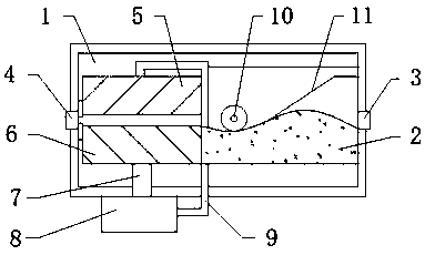
[0015] see figure 1 , figure 1 It is a structural schematic diagram of the present invention, an oiling device for a winding machine, including a device body 1, a wire outlet 4 is opened in the middle of the device body 1, and a wire inlet is opened in the middle of the right side surface of the device body 1 3. The inner side of the right side surface of the device body 1 is fixedly connected with a boss 2 by welding, and a pressure block 10 with a circular cro


PUM


Abstract

The invention discloses an oiling device for a winding machine, which comprises a device body. A wire outlet is opened in the middle of the device body. A wire inlet is opened in the middle of the right side surface of the device body. The inner side of the surface is fixedly connected with a boss by welding, the top of the boss is rotatably connected with a pressure block with a circular cross section, the inner side of the device body is fixedly connected with a guide piece by welding, and the groove provided in the device body The first sponge block is fixedly connected by adhesive, and the second sponge block is connected with the second sponge block under the first sponge block in the groove provided in the body of the device by adhesive fixation, and an oil return pipe is opened under the second sponge block, and the return The end of the lower surface of the oil pipe is fixedly connected with an oil supply device through a threaded screw, and the middle of the right side surface of the oil supply device is detachably connected with an oil delivery pipe through a threaded screw. The design is scientific and reasonable, the scheme is practical, and has high market promotion value .

Description


Claims


Application Information

Patent Timeline
Owner WUJIANG HONGRUI PRECISION MASCH FACTORY
Why Eureka
Try Eureka