Electric earthing switch arrangement for gas insulated substation

A gas-insulated, earthing switch technology, applied in earthing switches, electrical switches, switchgear and other directions, can solve problems such as expensive and expensive switches

Inactive Publication Date: 2018-03-27
GENERAL ELECTRIC TECH GMBH
View PDF4 Cites 0 Cited by
  • Summary
  • Abstract
  • Description
  • Claims
  • Application Information

AI Technical Summary

Problems solved by technology

[0007] Correspondingly, integrating said switches is very expensive as it requires additional design studies to determine where switches can be placed on lines and how to retrofit the compartments of these lines, dependin

Method used


Image

  • Electric earthing switch arrangement for gas insulated substation
  • Electric earthing switch arrangement for gas insulated substation
  • Electric earthing switch arrangement for gas insulated substation

Examples


Embodiment Construction

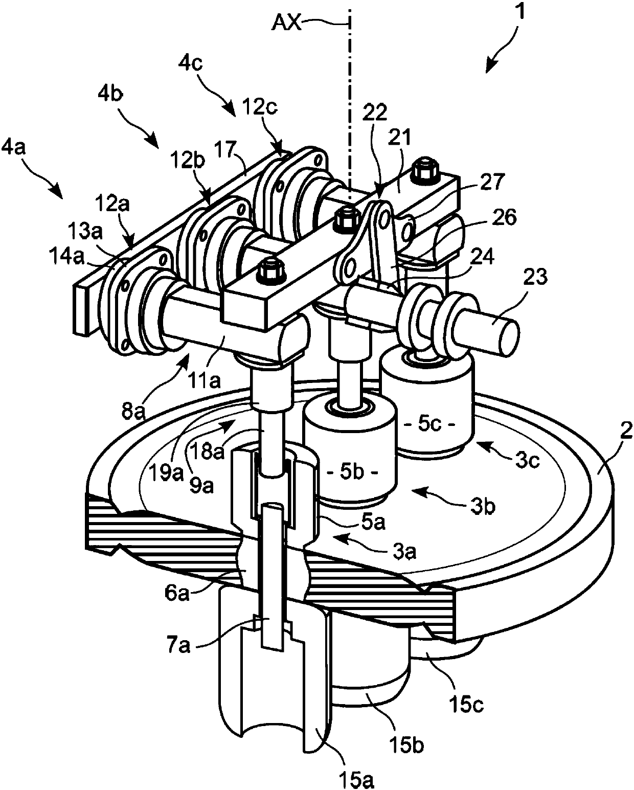
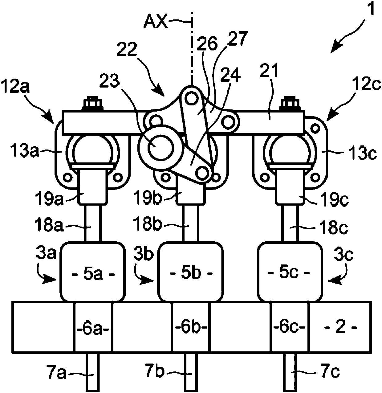
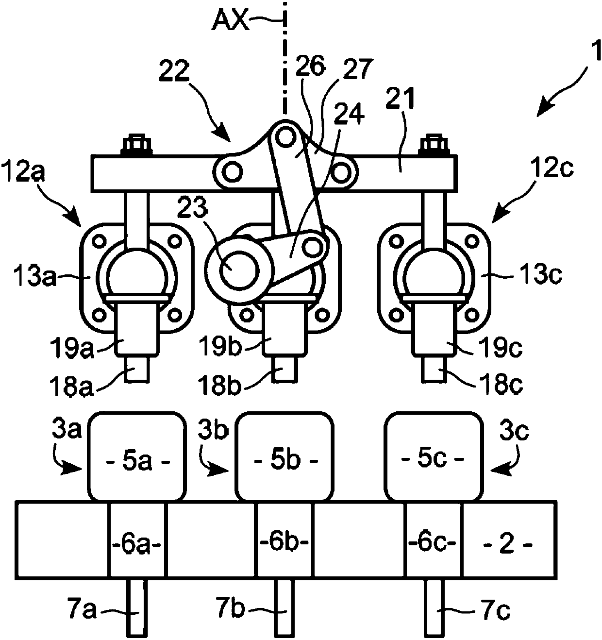
[0028] figure 1 The shown electrical earthing switch 1 according to the invention comprises a main insulating plate 2 which is substantially circular and carries three line contacts 3a, 3b, 3c. The example in the figures is a three-phase electrical grounding switch, but the invention is also applicable to single-phase or other types of multi-phase grounding switches.

[0029] The earthing switch 1 comprises three corresponding earthing contacts 4a, 4b, 4c, which are located in the switch such as figure 1 with figure 2 When closed as shown, it can make contact with the corresponding line contact 3a, 3b, 3c, or in the switch such as image 3 Disconnection is possible from these line contacts when open as shown.

[0030] In the following, the first line contact 3a and the first ground contact 4a will be described in more detail, their components and parts having reference symbols suffixed by the letter "a". Since the second and third contacts have the same part as the assembly,


PUM


Abstract

The invention relates to an electric earthing switch (1) to connect a line conductor of a gas insulated substation to the earth, comprising: -a metallic housing having two separate compartments: one,filled with insulating gas, for the main switch and the other, separated from insulating gas, for its drive mechanism, and a flange; -an insulating plate (2) to be tightened between the flange of thehousing and a flange of a compartment enclosing the line; -a line contact (3a, 3b, 3c) carried by the insulating plate (2) and having an insert portion with a thread bolt passing through the insulating plate (2); -a fixed earth contact (8a) passing through the wall of the housing and having an outer and an inner portion relatively to the housing; -a sliding earth contact (9a) carried by the fixedearth contact (8a) to slide relatively to this fixed earth contact (8a); -a mechanism to actuate the sliding earth contact (9a) between an open position and a closed position; -the fixed earth contact(8a) extending perpendicular to the sliding direction (AX).

Description


Claims


Application Information

Patent Timeline
Owner GENERAL ELECTRIC TECH GMBH
Why Eureka
Try Eureka