Insulation spacer for gas insulation electrical equipment

A technology of electrical equipment and insulation interval, which is applied in the setting of electrical components, switchgear, switchgear, etc. It can solve the problems of dangerous working state and short circuit of metal shell, etc., and achieve the effect of convenient and labor-saving use.

Pending Publication Date: 2022-01-07
叶传龙
View PDF1 Cites 0 Cited by
  • Summary
  • Abstract
  • Description
  • Claims
  • Application Information

AI Technical Summary

Benefits of technology

The technical effect of this patented design is improved safety during installation or maintenance operations for electrical equipment such as transformers due to its ability to securely hold an insulator inside it without requiring excessive force from outside pressure sources like springs. This ensures better stability and reduces potential hazards caused by external forces acting upon the device's components.

Problems solved by technology

This patented technical problem addressed in this patents relates to improving the safety during operation when separating or filling gases inside certain types of gas-filled electrically power devices (GIS).

Method used


Image

  • Insulation spacer for gas insulation electrical equipment
  • Insulation spacer for gas insulation electrical equipment
  • Insulation spacer for gas insulation electrical equipment

Examples


Embodiment Construction

[0028] The following will clearly and completely describe the technical solutions in the embodiments of the present invention with reference to the accompanying drawings in the embodiments of the present invention. Obviously, the described embodiments are only some, not all, embodiments of the present invention. Based on the embodiments of the present invention, all other embodiments obtained by persons of ordinary skill in the art without making creative efforts belong to the protection scope of the present invention.

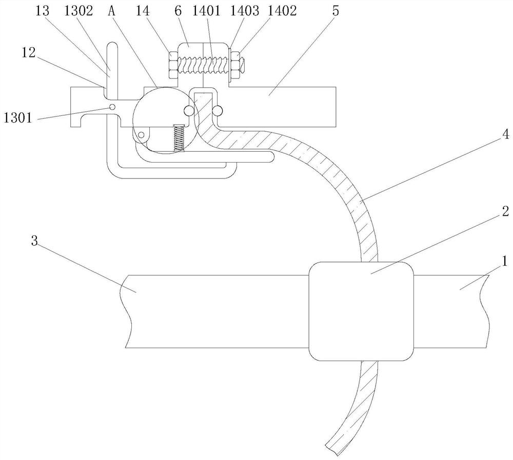
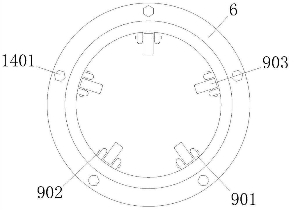
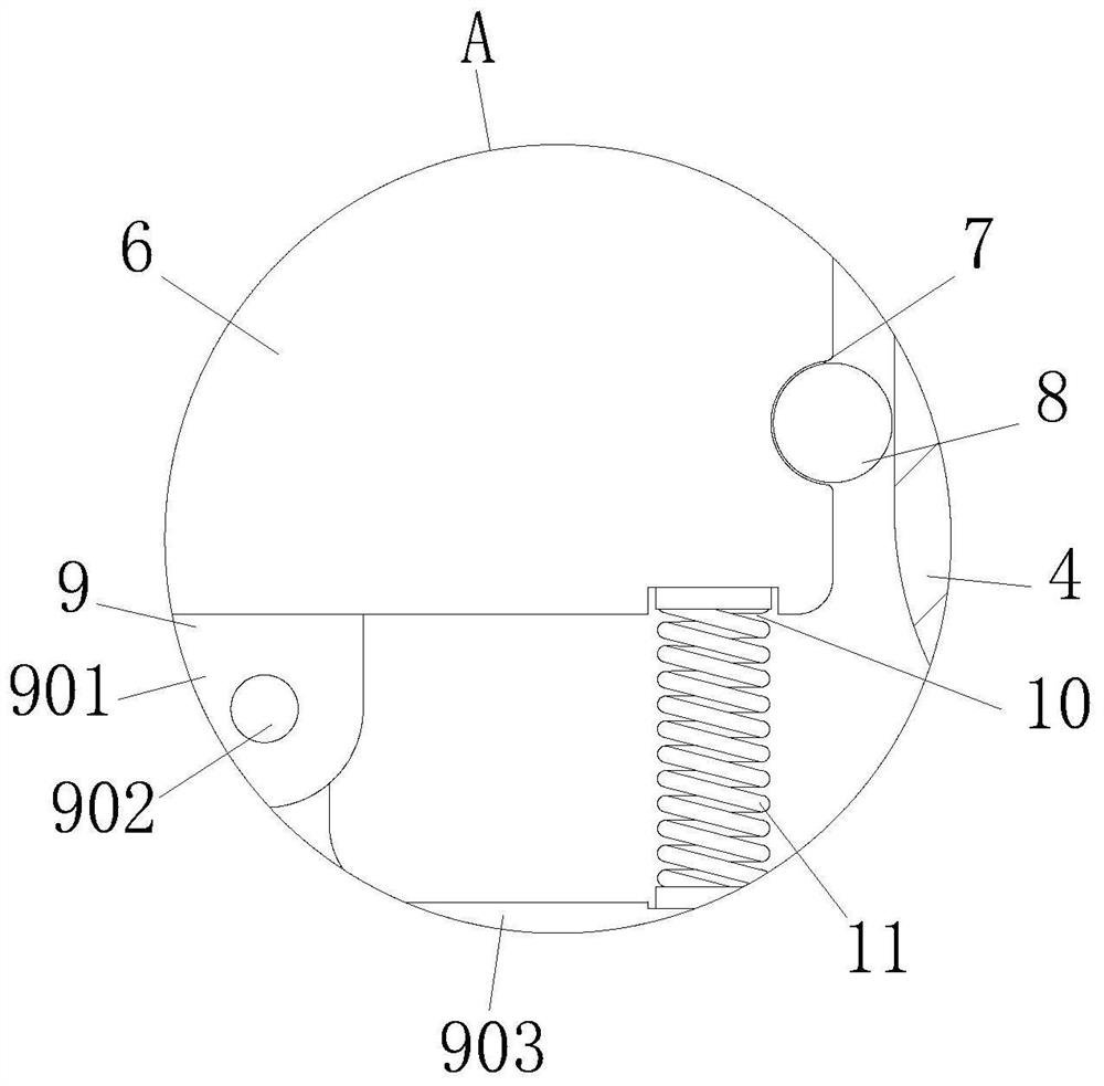
[0029] see Figure 1-5 , an insulating spacer for gas-insulated electrical equipment, comprising a first lead 1, one end of the first lead 1 is fixedly connected with a connecting lead 2, one end of the connecting lead 2 is fixedly connected with a second lead 3, and the outer wall of the connecting lead 2 is fixed The spacer body 4 is connected, the outer wall of the spacer body 4 is movably connected with a first flange 5, one side of the first flange 5 is mova


PUM


Abstract

The invention belongs to the technical field of insulation spacers, and discloses an insulation spacer for gas insulation electrical equipment. The insulation spacer comprises a first wire, one end of the first wire is fixedly connected with a connecting wire, and one end of the connecting wire is fixedly connected with a second wire. Through a movable mechanism, a spacer body can be completely clamped on the inner wall of a first flange, so that the spacer body can be completely squeezed towards the outer wall of the first flange by a clamping block through a rebound spring after working, and the space formed between the spacer body and the first flange and the space formed between the spacer body and the second flange are completely squeezed; meanwhile, due to the arrangement of a mounting groove and a sealing ring, the edge of the spacer body is sealed, a completely-closed space is formed, and a safer working environment can be provided for the first wire and the second wire in subsequent use; and when the spacer body is squeezed, the spacer body can be easily fixed on the inner wall of the first flange through the clamping block, so that the insulation spacer is convenient and labor-saving to use.

Description


Claims


Application Information

Patent Timeline
Owner 叶传龙
Why Eureka
Try Eureka