Injection-mold conveying mechanism with exhaust gas shield

A conveying mechanism and finished product technology, which is applied in the field of plastic processing, can solve the problems of physical injury, severe human injury, and hair loss of workers, and achieve the effects of reducing work intensity, reducing air pollution, and improving work efficiency

Inactive Publication Date: 2016-02-03
CHONGQING YAQIAN BUILDING MATERIAL CO LTD
View PDF0 Cites 1 Cited by
  • Summary
  • Abstract
  • Description
  • Claims
  • Application Information

AI Technical Summary

Benefits of technology

This new injector system has an automatic receiving device for deliverings that prevents particles or vapor emissions during production. It also includes a collective covering over the entire injection molder's surface where it helps absorb any small droplets produced while melting plastic material into solid form without being exposed directly towards humans. By doing this, there will be fewer peoples who may get hurt due to exposure to these tiny parts.

Problems solved by technology

This patented technical problem addressed by this patents relates to how much harmful particulate matter from plasma melting machines causes environmental damage during operations that require manual handling or cleanliness. Existing methods involve exhaustion with no effective solution being developed yet.

Method used


Image

  • Injection-mold conveying mechanism with exhaust gas shield
  • Injection-mold conveying mechanism with exhaust gas shield

Examples


Embodiment Construction

[0016] The invention will be further described in detail below in conjunction with the accompanying drawings and specific embodiments.

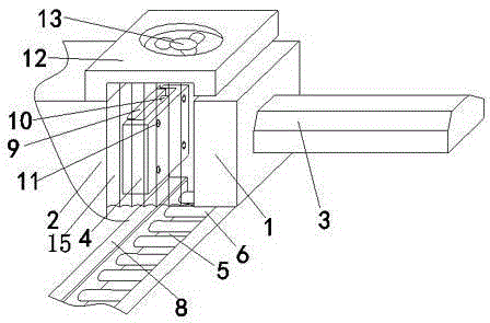
[0017] Such as figure 1 Shown is a schematic structural view of the injection molding product delivery mechanism provided with exhaust gas protection in the present invention; an injection molding product delivery mechanism provided with exhaust gas protection in the present invention includes an injection molding machine base, a fixed frame 2 arranged on the base and a movable Frame 1, described fixed frame 2 is provided with left mold 4, and described movable frame 1 is provided with the right mold that forms mold cavity with left mold, and described left mold 4 is provided with demoulding device and is used for fixing The mounting hole of the plastic product, the left mold 4 is provided with a track below, and the track 5 extends out of the machine base, and the track 5 includes mounting seats 8 arranged on both sides and transport rollers ar


PUM


Abstract

The invention provides an injection-product conveying mechanism with an exhaust gas shield. The injection-product conveying mechanism comprises an injection machine base, a fixed machine frame and a movable machine frame, wherein the fixed machine frame and the movable machine frame are arranged on the base; the fixed machine frame is provided with a left mold; a right mold is arranged on the movable machine frame, wherein the left mold and the right mold form a mold cavity; a demolding device is arranged on the left mold, and a mounting hole for fixing a finished plastic product is formed in the left mold; a rail is arranged at a lower position between the movable machine frame and the fixed machine frame, and extends out of the base; the rail comprises mounting bases which are respectively arranged on two sides of the rail, and conveying rollers arranged between the mounting bases; a transmission device is arranged in each mounting base; a collecting cover which extends to the upper position of the mold cavity is arranged at the top of the fixed machine frame; a fan is arranged at the top of the collecting cover, and communicates with an exhaust pipe; gas insulation curtains are respectively arranged on the front side of the collecting cover and the rear side of the collecting cover. The injection-product conveying mechanism disclosed by the invention can automatically receive and convey injection products, so that the situation that operators need to approach to the injection molds to fetch the injection products is avoided, and the hurt of smoke with particles to human bodies is avoided; besides, the labor strength of workers is reduced, and the working efficiency is improved.

Description


Claims


Application Information

Patent Timeline
Owner CHONGQING YAQIAN BUILDING MATERIAL CO LTD
Why Eureka
Try Eureka