High-temperature fluidized bed reaction device

A high-temperature fluidized bed and reaction device technology, applied in chemical/physical processes, chemical instruments and methods, etc., can solve problems such as the difficulty of implementing a fluidized bed device, and achieve the effect of symmetrical and uniform air flow

Pending Publication Date: 2018-04-13
INST OF METAL RESEARCH - CHINESE ACAD OF SCI
View PDF0 Cites 6 Cited by
  • Summary
  • Abstract
  • Description
  • Claims
  • Application Information

AI Technical Summary

Problems solved by technology

However, in some applications (such as metal deposition, such as the preparation of high-quality graphene on non-metallic substrates, etc.), the reactio

Method used


Image

  • High-temperature fluidized bed reaction device
  • High-temperature fluidized bed reaction device
  • High-temperature fluidized bed reaction device

Examples


Embodiment 1

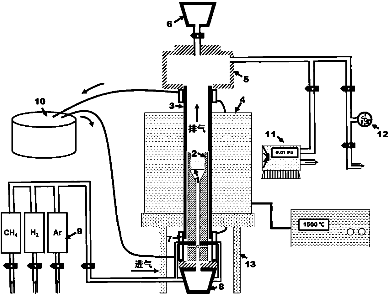
[0041] In this embodiment, the size of each component of the heating device is designed and processed according to the actual situation according to the drawing matching, and the real object is as follows Figure 7 shown.

[0042] In the embodiment, the high-temperature heating furnace body can be heated to 2000° C., and the heating furnace is placed on the furnace body support 13 . In the embodiment, the high-temperature-resistant furnace tube 3 is a high-temperature-resistant corundum furnace tube with an outer diameter of 50 mm, an inner diameter of 40 mm, and a tube length of 120 cm. The two ends of the furnace tube are hermetically connected by a set of fast-loading and dismounting flanges (upper sealing flange and lower sealing flange).

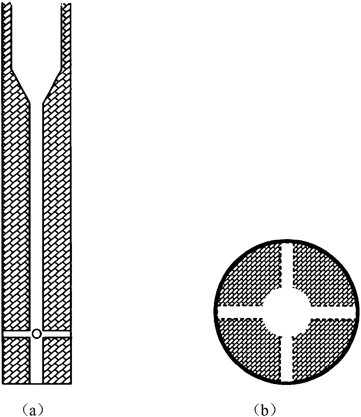
[0043] In the embodiment, the high-temperature-resistant lined airflow regulator is made of graphite. The reactor is a cylindrical hollow structure with an outer diameter of 39.5 mm, which precisely matches the inner diameter of the furn


PUM

PropertyMeasurementUnit
Mesh apertureaaaaaaaaaa

Abstract

The invention discloses a high-temperature fluidized bed reaction device, and belongs to the technical field of powder material production. The device comprises a high-temperature heating furnace body, a feeding cabin, an upper sealing flange, a high-temperature-resistance furnace pipe, an airflow regulator, and air distributor, a lower sealing flange and a discharging cabin, wherein the inner cavity of the high-temperature-resistance furnace pipe is served as a fluidized bed reaction cavity; the feeding cabin is connected with the top end of the high-temperature-resistance furnace pipe through the upper sealing flange; the bottom end of the high-temperature-resistance furnace pipe is connected with the discharging cabin through the lower sealing flange; the airflow regulator and the gas distributor are arranged in the high-temperature-resistance furnace pipe. According to the device, power material fluidization can be realized under a high-temperature environment, and the problems ofthe powder layering, hardening and the like of a conventional device in a reaction process due to an uneven atmosphere condition are avoided. Meanwhile, since a controllable feeding cabin and a controllable discharging cabin are designed, continuous material loading and unloading and quick material cooling can be realized, production efficiency is greatly improved, and production cost is lowered.

Description


Claims


Application Information

Patent Timeline
Owner INST OF METAL RESEARCH - CHINESE ACAD OF SCI
Why Eureka
Try Eureka