Outdoor rainproof and snow-protecting distribution box cabinet

A power distribution cabinet, anti-rain and snow technology, applied in substation/power distribution device casing, electrical components, substation/switch layout details, etc., can solve the problems of power distribution cabinet service life and working stability that are easily affected by the environment , to achieve the effect of reducing the excessive pressure on the box

Active Publication Date: 2018-04-20
高原(山东)机电设备有限公司
View PDF2 Cites 10 Cited by
  • Summary
  • Abstract
  • Description
  • Claims
  • Application Information

AI Technical Summary

Benefits of technology

This patented technology describes an improved power distributing system for people who live or worked at high altitudes where they may be exposed to severe weather conditions such as frost and snowfall during winter months when temperatures can fall below freezing (F). It includes various features like a pillow covering over the top part of the housing, support devices surrounding the pillows, electrical telescopes inside the mechanism, scrapers pushing them towards the snow, sensors detecting if any damage has occurred due to snow buildup, controller circuits activated through these components, thermal resistant wires used to melt snow off surfaces, and drier boxes containing hot air bags to keep warm keeping the interior space properly. Additionally, there're also included pressure columns within the case to help balance pressurized areas caused by snow falling onto the structure. Overall, this technical solution improves safety measures against extreme environmental factors and provides better performance than existing systems.

Problems solved by technology

This patented technical problem addressed in this patents relates to improving heat dissipation for electronic devices used with high voltage electricity systems such as Power Distribution Cabins (PDCs). Specifically, it highlighted how long periods can lead to damage or failure from frost buildup caused by excessive moisture condensations during winter months when temperatures outside their normal range fall below certain levels.

Method used


Image

  • Outdoor rainproof and snow-protecting distribution box cabinet
  • Outdoor rainproof and snow-protecting distribution box cabinet
  • Outdoor rainproof and snow-protecting distribution box cabinet

Examples


Embodiment Construction

[0022] In order to make the purpose, technical solutions and advantages of the embodiments of the present invention more clear, the technical solutions in the embodiments of the present invention will be clearly and completely described below in conjunction with the drawings in the embodiments of the present invention. Apparently, the described embodiments are some, but not all, embodiments of the present invention. Based on the embodiments of the present invention, all other embodiments obtained by persons of ordinary skill in the art without creative efforts fall within the protection scope of the present invention.

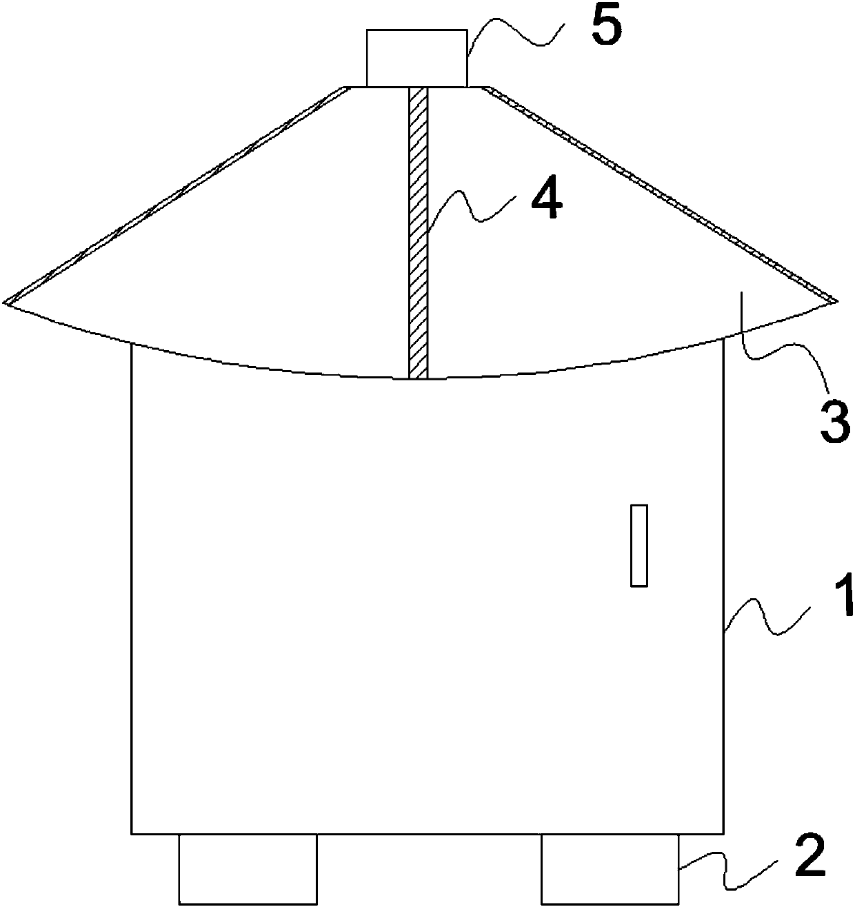
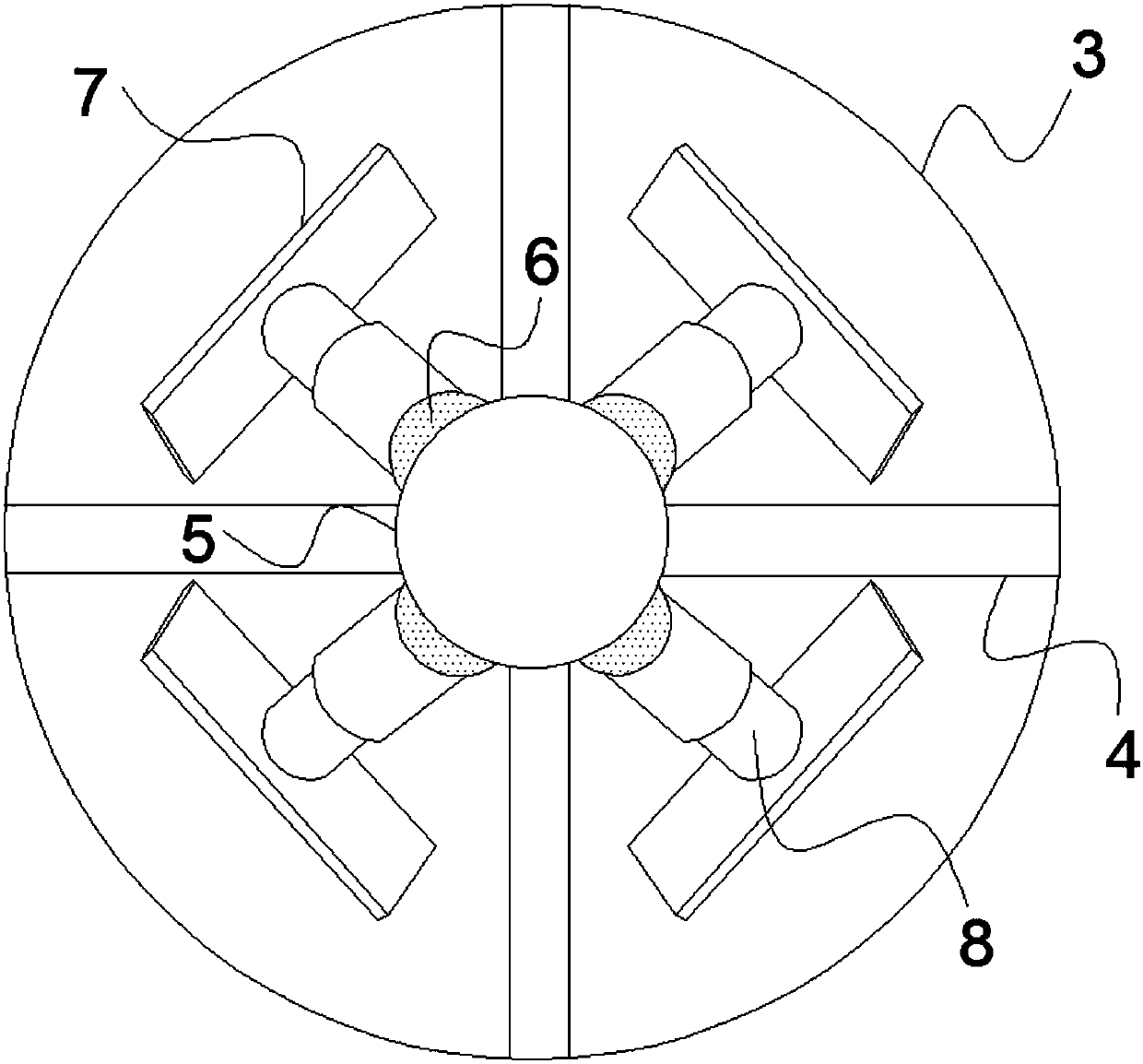
[0023] A mixing device for veterinary medicine, such as Figure 1-3 As shown, the box body 1 is included, and the left and right sides of the bottom of the box body 1 are symmetrically provided with a shockproof base 2, and the top of the box body 1 is provided with a flat top box cover 3, and the top of the flat top box cover 3 is provided with a pillar 5, and th


PUM


Abstract

The invention relates to the technical field of electric power, specifically to an outdoor rainproof and snow-protecting distribution box cabinet. The outdoor rainproof and snow-protecting distribution box cabinet includes a box body, left and right sides of the bottom of the box body are symmetrically provided with shockproof pedestals, the top of the box body is provided with a flat-top box cover, the top of the flat-top box cover is provided with a pillar, and four waterproof pipelines are buried in a radial direction of the flat-top box cover at uniform intervals; four support devices arearranged on the outer wall of the periphery of the pillar at uniform intervals, the four support devices and the four waterproof pipelines are arranged in a staggered manner, the bottoms of the support devices are in through connection with electric telescopic rods, the tops of the electric telescopic rods are connected with the tops of the inner cavities of the support devices, and the bottoms ofthe electric telescopic rods are connected with scraper plates; and the inner cavities of the waterproof pipelines are provided with heating resistance wires, and the inner wall of the flat-top box cover and the top of the box body are connected through three pressure columns arranged at intervals. The outdoor rainproof and snow-protecting distribution box cabinet provided by the invention can effectively overcome the defects existing in the prior art that the service life and working stability of a distribution cabinet are easy to affect by environment in arctic-alpine regions.

Description


Claims


Application Information

Patent Timeline
Owner 高原(山东)机电设备有限公司
Why Eureka
Try Eureka