Architecture based on topology configuration of BMC change system and cascade configuration method

A topology and cascading technology, applied in the server field, can solve problems such as unfavorable user operation, jumping cap falling off, etc., to achieve the effect of convenient operation

Active Publication Date: 2018-05-11
ZHENGZHOU YUNHAI INFORMATION TECH CO LTD
View PDF8 Cites 2 Cited by
  • Summary
  • Abstract
  • Description
  • Claims
  • Application Information

AI Technical Summary

Benefits of technology

The technology described by this patented allows servers with multiple types of hardware components (BMC) to communicate without having any wires or cables connected through them. This makes it easier than previous methods like connecting signals directly into specific pins on each component's circuit board. Users don’t have to physically access these connections when changing their machine settings because they only needed one connection instead.

Problems solved by technology

This technical problem addressed by this patented technology relates to improving computer systems' ability to handle increasingly complex applications such as video processing or virtual reality simulations that demand more memory than previous generations of computers. These new technologies often involve higher speeds and increased data transfer rates from one component into another component called an interface card. However, existing architectures are limited because they only allow certain types of connections like xlene circuits without any extra space needed for other components. Therefore, there needs to be some way to efficiently manage these connections while still ensuring proper functionality across different scenarios.

Method used


Image

  • Architecture based on topology configuration of BMC change system and cascade configuration method
  • Architecture based on topology configuration of BMC change system and cascade configuration method
  • Architecture based on topology configuration of BMC change system and cascade configuration method

Examples


Embodiment Construction

[0045] In order to make the purpose, features and advantages of the present invention more obvious and understandable, the technical solutions protected by the present invention will be clearly and completely described below using specific embodiments and accompanying drawings. Obviously, the implementation described below Examples are only some embodiments of the present invention, but not all embodiments. Based on the embodiments in this patent, all other embodiments obtained by persons of ordinary skill in the art without creative efforts fall within the protection scope of this patent.

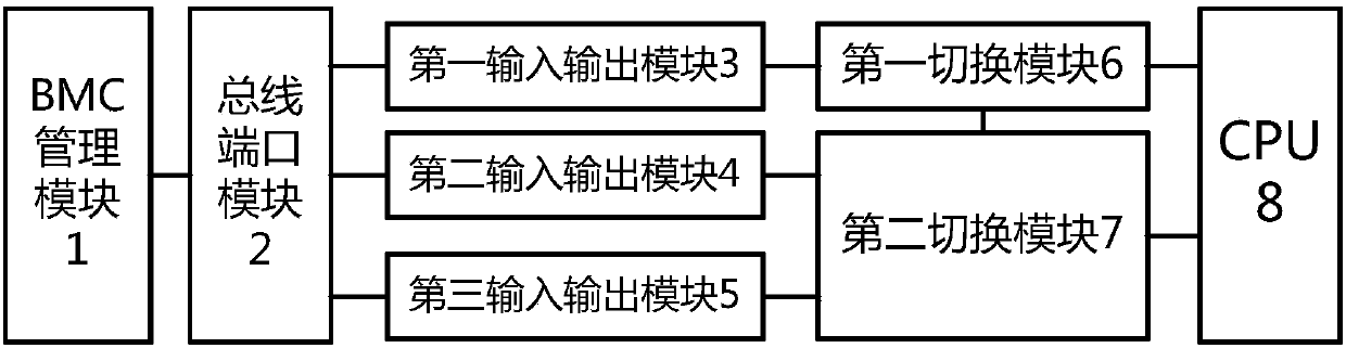
[0046] The present invention provides a framework for changing system topology configuration based on BMC, such as figure 1 As shown, it includes: BMC management module 1, bus port module 2, first input and output module 3, second input and output module 4, third input and output module 5, first switching module 6, second switching module 7 and CPU8;

[0047] The signal output end of the BMC


PUM


Abstract

The invention provides architecture based on the topology configuration of a BMC change system and a cascade configuration method. The signal output end of a BMC management module is connected with the signal input end of a bus port module, the bus port module is connected with the signal input end of a first input-output module, the signal output end of the first input-output module is connectedwith the signal input end of a first switching module, a second input-output module is connected with the first signal input end of a second switching module, and a third input-output module is connected with the second signal input end of the second switching module. Different configurations can be switched through the BMC management module, and application to different scenes of servers is achieved. The situation that in an existing scheme, STARP pins are in signal connection to 3-pin jumper caps, and in practical use, topological structures can be changed only in the manner that a user needs to reach the scene to open a case and manually adjusts the positions of the jumper caps is avoided. Chip port state configurations can be changed, and operation of the user is facilitated.

Description


Claims


Application Information

Patent Timeline
Owner ZHENGZHOU YUNHAI INFORMATION TECH CO LTD
Why Eureka
Try Eureka