Gas-liquid separation mechanism capable of monitoring gas concentration

A gas-liquid separation and gas concentration technology, applied in the preparation of test samples, etc., can solve the problems of affecting the gas concentration efficiency in the detection liquid, cumbersome separation process, complex structure, etc. simple effect

Inactive Publication Date: 2018-05-25
曾国春
View PDF0 Cites 0 Cited by
  • Summary
  • Abstract
  • Description
  • Claims
  • Application Information

AI Technical Summary

Benefits of technology

This patented device simplifies its design by allowing two different types of liquids (liquid) from separate pipes into one tube that flows along an annular path within it's housing while being filtered separately before entering another chamber where they react together inside a specific part called the sensors or detector. By connecting these tubings at opposite ends, this device becomes more efficient than traditional methods due to larger filter areas and higher gases collectability compared to previous designs. Additionally, there may also have a special type of drainage system used when draining any remaining fluid after each use period. Overall, this new technology improves detection accuracy and reduces damage caused during operations over time.

Problems solved by technology

This patented technical problem addressed by this patents relates to finding faulty gases that may be present during production or processing operations when analyzed liquids containing these gases are being processed. These faulties can lead to decreased productivity due to poor detection accuracy caused by complicated systems with multiple components.

Method used


Image

  • Gas-liquid separation mechanism capable of monitoring gas concentration

Examples


Embodiment

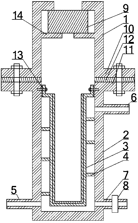
[0018] Such as figure 1 As shown, the gas-liquid separation mechanism that can monitor the gas concentration includes an upper shell 1, a lower shell 2, and a gas-liquid filter diaphragm 3, wherein the upper shell 1 forms a drum shape with an open lower end, and the lower shell 2 forms an upper end. Open barrel shape, the upper end of the lower housing 2 is sealed and connected with the lower end of the upper housing 1 , the gas-liquid filter membrane 3 is arranged in the lower housing 2 , and its upper end is sealed and connected with the inner wall of the lower housing 2 . A gas cavity is formed between the upper shell 1, the lower shell 2, and the gas-liquid filter diaphragm 3, and a transition chamber is formed between the lower shell 2 and the gas-liquid filter diaphragm 3. The upper and lower sides of the lower shell 2 A liquid outlet pipe 6 and a liquid inlet pipe 5 are respectively arranged on the wall, and both the liquid outlet pipe 6 and the liquid inlet pipe 5 are con


PUM


Abstract

The invention discloses a gas-liquid separation mechanism capable of monitoring gas concentration. The gas-liquid separation mechanism comprises an upper casing, a lower casing and a gas-liquid filtration diaphragm, wherein the upper end of the lower casing is connected with the lower end of the upper casing, the gas-liquid filtration diaphragm is arranged in the lower casing and has the upper endconnected with the inner side wall of the lower casing, a transition cavity is formed between the lower casing and the gas-liquid filtration diaphragm, the upper casing, the lower casing and the gas-liquid filtration diaphragm constitute a gas accommodating cavity, a liquid inlet pipe and a liquid drain pipe which are communicated with the transition cavity are arranged on the side wall of the lower end of the lower casing, a stop valve is arranged on the liquid drain pipe, and a liquid outlet pipe communicated with the transition cavity is arranged on the side wall of the upper end of the lower casing. Spiral isolation plates wind around the outer side wall of the gas-liquid filtration diaphragm and divide the transition cavity to form spiral channels communicated with the liquid inlet pipe and the liquid drain pipe. The mechanism is simple in overall structure, convenient to implement and convenient to operate and high in separation efficiency when separating gas in a liquid, and thus, the detection efficiency of gas in the liquid can be improved.

Description


Claims


Application Information

Patent Timeline
Owner 曾国春
Why Eureka
Try Eureka