Anti-collision device for shield machine trolley

An anti-collision, shield machine technology, applied in the field of tunnel shield engineering, can solve problems such as deformation of support force, affecting the work of shield machine, etc.

Pending Publication Date: 2018-06-05
辽宁三三工业有限公司
View PDF0 Cites 1 Cited by
  • Summary
  • Abstract
  • Description
  • Claims
  • Application Information

AI Technical Summary

Problems solved by technology

However, because of the rigid collision, the traction rod connected to the trolley and the rear

Method used


Image

  • Anti-collision device for shield machine trolley
  • Anti-collision device for shield machine trolley

Examples


Embodiment Construction

[0005] In order to achieve the above object, technical solution of the present invention is achieved in that way:

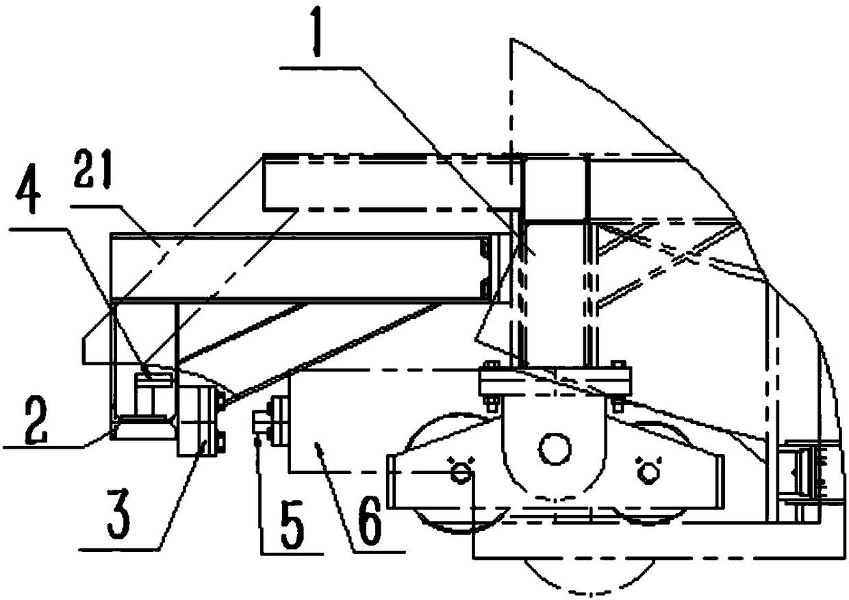
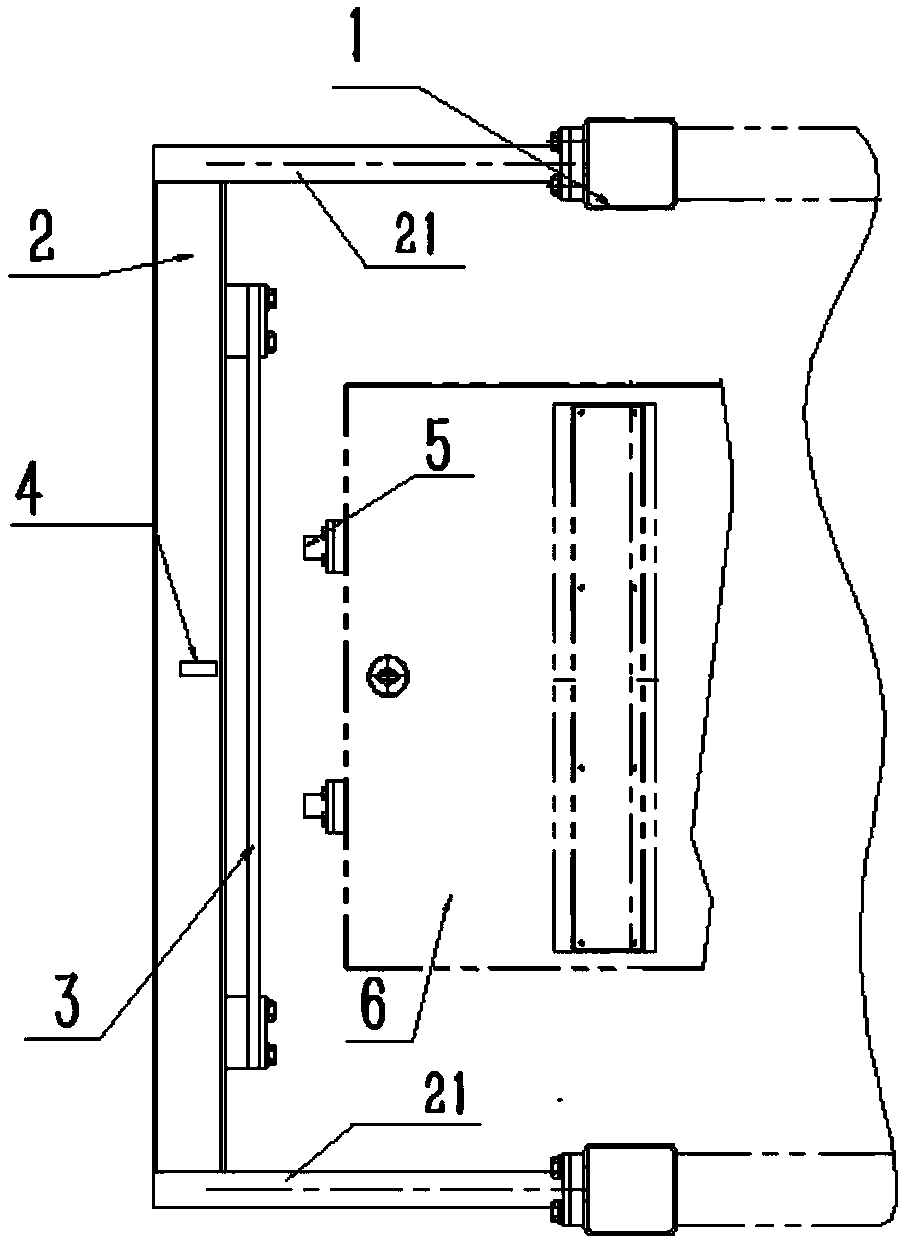
[0006] An anti-collision device for a trolley of a shield machine, including an anti-collision beam and a spring steel plate; the anti-collision beam is horizontally arranged in front of the trolley, and the left and right side walls of the upper end of the anti-collision beam pass through the fixed arm and the left and right sides of the trolley respectively. The beam corresponds to the fixed connection; there is a spring steel plate on the surface of the anti-collision beam, and the spring steel plate faces the feeding movement direction of the level car, and a reflective laser sensor is installed in the middle of the anti-collision beam, which illuminates the feeding movement direction of the level car , The reflective laser sensor is connected with the distance alarm.

[0007] In the practical application of the present invention, the trolley has an inverted U-s


PUM


Abstract

The invention provides an anti-collision device for a shield machine trolley. The anti-collision device comprises an anti-collision beam and a steel spring plate; the anti-collision beam is horizontally arranged in front of the trolley, the left side wall and the right side wall of the upper end of the anti-collision beam are correspondingly and fixedly connected with a left boundary beam and a right boundary beam of the trolley through fixed arms; the steel spring plate is arranged on the surface of the anti-collision beam in the face of a feeding movement direction of an electric flat car; areflective laser sensor is arranged in the middle part of the anti-collision beam; the reflective laser sensor irradiates to the feeding movement direction of the electric flat car, and the reflective laser sensor is connected with a distance warner. The anti-collision device for the shield machine trolley disclosed by the invention can give out an early warning when the electric flat car entersthe collision dangerous range, thereby prompting a worker to operate a brake device; and meanwhile, the collision strength is effectively reduced, the deformation on the equipment caused by the collision is reduced, the equipment normal work is realized, and the maintenance quantity is reduced.

Description


Claims


Application Information

Patent Timeline
Owner 辽宁三三工业有限公司
Why Eureka
Try Eureka