Laser projector shell

A technology for laser projectors and casings, which is applied in optics, instruments, projection devices, etc., can solve the problem that the combination configuration scheme of the shape cannot be quickly adjusted and replaced, and achieve the effect of improving the appearance and being cheap.

Pending Publication Date: 2018-06-15
中航国画(上海)激光显示科技有限公司
View PDF0 Cites 0 Cited by
  • Summary
  • Abstract
  • Description
  • Claims
  • Application Information

AI Technical Summary

Benefits of technology

In this new design that uses two layers instead of one it allows quick changes when changing ornamental designs without having to replace entire products at once. It also includes different types of materials like metals or plastisol coatings which make them more durable over time compared to traditional methods such as painting. Additionally, there may include other features like adding texture elements onto the outside of the trim panel itself (such as embroidery) to enhance its overall look). Overall, these improvements help reduce costs while still maintaining an attractive visual appeal.

Problems solved by technology

Technological Problem: Current projection housings use either metallic part alone or plastified platy construction, but they don’t match up well when replacing different colors like silver gray. Additionally, current designs require multiple steps before being able to change color appearances without affecting the overall look quality of the final product.

Method used


Image

  • Laser projector shell
  • Laser projector shell
  • Laser projector shell

Examples


Embodiment Construction

[0028] Below in conjunction with accompanying drawing, structure and working process of the present invention will be further described.

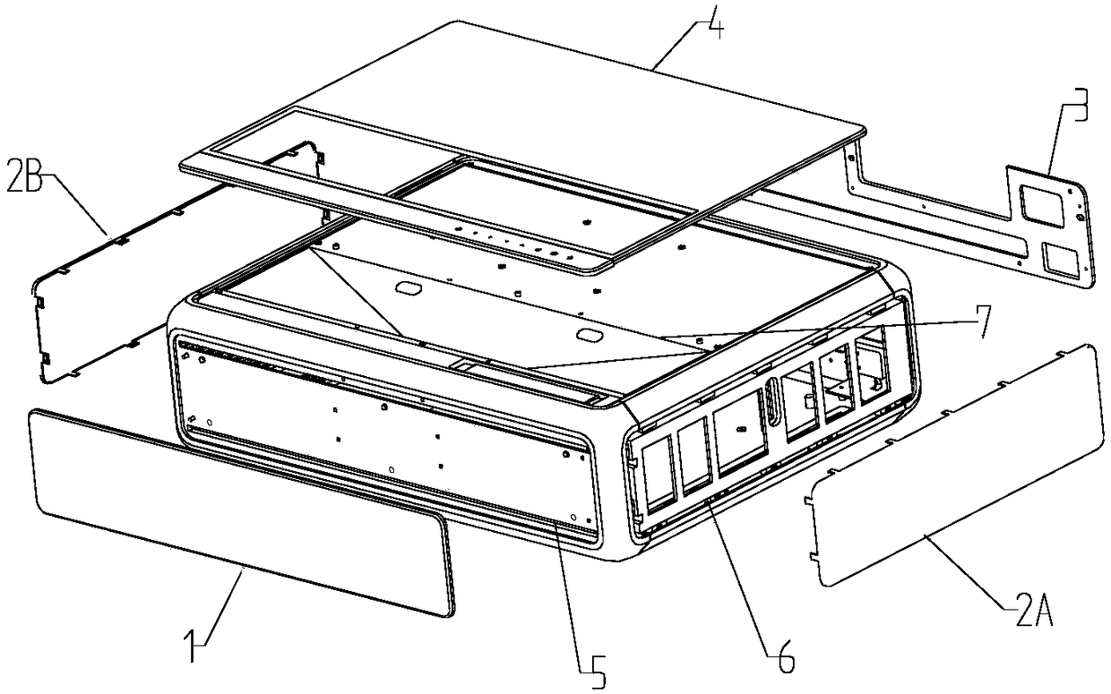
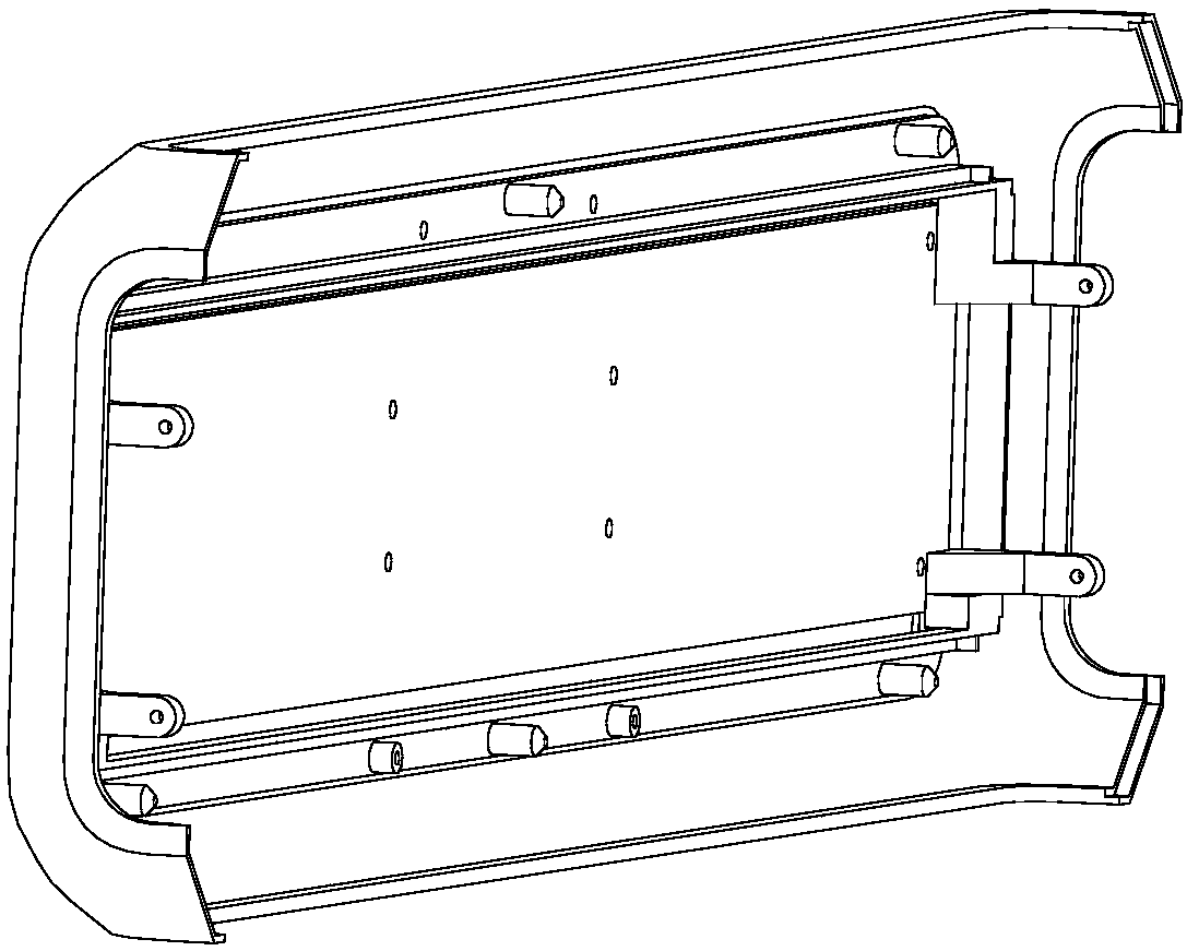
[0029] Such as Figure 1 to Figure 8 As shown, a laser projector casing includes an inner casing and an outer decorative panel, and a connecting mechanism connected to the inner casing is provided on the inner side of the outer decorative panel, wherein the inner casing includes a bottom plate 9, an upper cover 7, and a front cover 5 , rear cover 8, left side plate 6A, right side plate 6B, fixed connection (or be fixed with screw) between left side plate 5A and right side plate 6B and base plate 9; , rear cover 8, left side panel 6A, right side panel 6B are correspondingly assembled upper trim panel 4, front trim panel 1, rear trim panel 3, left trim panel 2A, right trim panel 2B.

[0030] It also includes a decorative frame strip 10, and the decorative frame strip 10 is arranged at the joint between two adjacent surfaces.

[0031] Between t


PUM


Abstract

The invention discloses a laser projector shell. The laser projector shell comprises an inner case and an outer decoration plate; the inner side of the outer decoration plate is provided with a connection mechanism connected with the inner case; the inner case comprises a bottom plate, an upper cover, a front cover, a rear cover, a left side plate and a right side plate; the left side plate and the right side plate are fixedly connected with the bottom plate or assembled to the bottom plate through screws; and the outer decoration plate includes an upper decoration plate, a front decoration plate, a back decoration plate, a left decoration plate, and a right decoration plate which are correspondingly assembled onto the upper cover, the front cover, the rear cover, the left side plate and the right side plate. According to the laser projector shell of the invention, a double-layer structure is adopted; decorative parts are located at the outer layer of the double-layer structure; the structural parts are arranged at the inner layer of the double-layer structure; and the outer decorative parts can be replaced, so that the rapid adjustment of the material, appearance part combinationschemes and cost of products can be realized.

Description


Claims


Application Information

Patent Timeline
Owner 中航国画(上海)激光显示科技有限公司
Why Eureka
Try Eureka