Spinning system and use method thereof
A hemp fiber and frame technology, applied in the field of spinning systems, can solve the problems of difficult mixing and sticking, affecting processing, poor quality, etc., and achieve the effect of increasing the sticking effect
- Summary
- Abstract
- Description
- Claims
- Application Information
AI Technical Summary
Problems solved by technology
Method used
Image

Examples
Embodiment 1
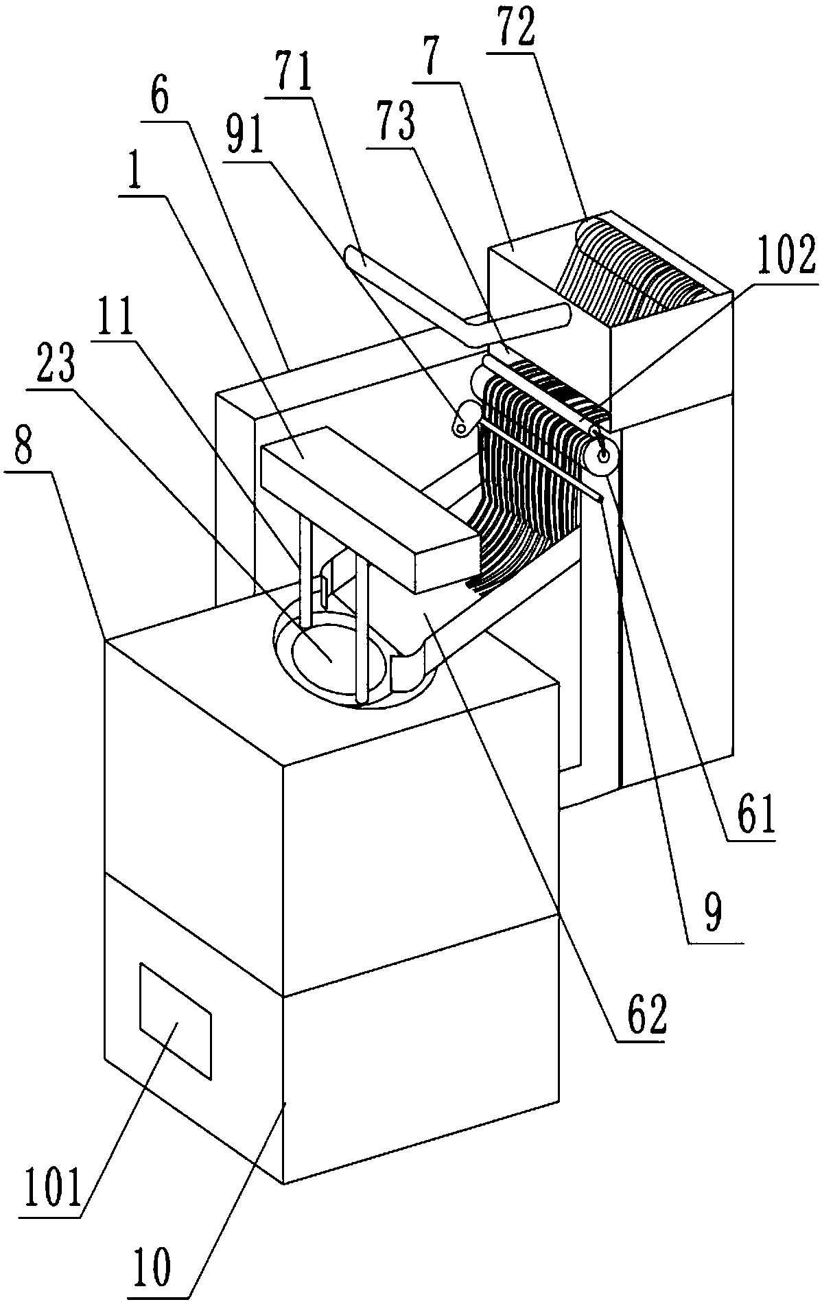
[0038] Such as figure 1 , figure 2 , image 3 , Figure 4 and Figure 5 Shown, in order to achieve the above object, basic scheme of the present invention is as follows:
[0039] A spinning system, comprising a frame 6, a cleaning part, a transfer part and a cutting part 8; the cleaning part, the transfer part and the cutting part 8 are all connected to the frame 6; the frame 6 is figure 1 L shape shown. The cleaning section comprises a cleaning box 7, a blowpipe 71 and a fiber roll 72 wound with hemp fiber, and the cleaning box 7 is fixed on the top of the frame 6; the fiber roll 72 is rotatably connected on the cavity wall of the cleaning box 7; the cleaning box 7 is away from the fiber One side of roller 72 is provided with the opening 73 that passes through for hemp fiber, and blowing pipe 71 is positioned at the top of opening 73; The transitional roller 61 that passes through for hemp fiber is also provided on the frame 6, and the below of transitional roller 61 is prov
Embodiment 2
[0049] A method for using a spinning system, comprising the steps of:
[0050] Step 1, feeding: wind the hemp fiber on the fiber roller 72, pull the hemp fiber between the transition roller 61 and the squeeze roller 102, and then pass through the transmission rod 9;
[0051] Step 2, impurity removal: start the blowing pipe 71, and the blowing pipe 71 blows and cleans the hemp fibers in the cleaning box 7, so that the impurities are blown out from the gaps of the hemp fibers;
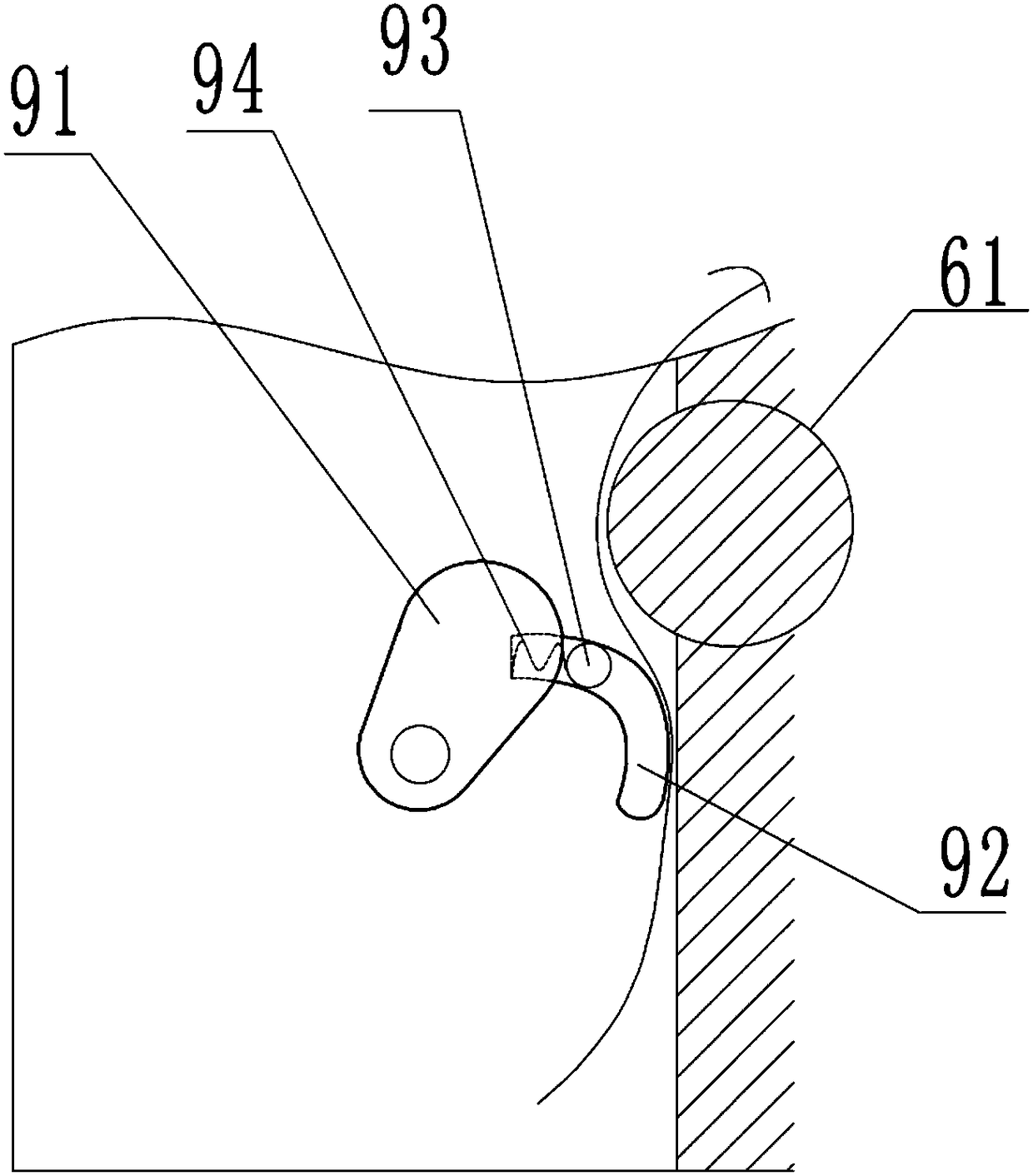
[0052] Step 3, transmission: start the power unit, the power unit drives the cam 91 to rotate, and the cam 91 presses the transmission rod 9 in the process of rotation, and the transmission rod 9 moves along the arc-shaped slideway 92 towards the direction close to the hemp fiber and moves the hemp fiber Pressed onto the frame 6, the cam 91 continues to press the transmission rod 9, and the transmission rod 9 moves downward along the arc-shaped slideway 92, thereby realizing the downward transmission of the
PUM
 Abstract
Description
Claims
Application Information
 - R&D Engineer
- R&D Manager
- IP Professional
- Industry Leading Data Capabilities
- Powerful AI technology
- Patent DNA Extraction
Browse by: Latest US Patents, China's latest patents, Technical Efficacy Thesaurus, Application Domain, Technology Topic.
© 2024 PatSnap. All rights reserved.Legal|Privacy policy|Modern Slavery Act Transparency Statement|Sitemap