Cracking equipment

A technology of equipment and combustion cylinder, applied in the field of organic matter cracking, can solve the problems of low heat transfer efficiency, energy waste, unfavorable organic matter cracking, etc. Effect

Pending Publication Date: 2019-12-17
ZHAOYUAN HUICHAO NEW ENERGY TECH CO LTD
View PDF0 Cites 3 Cited by
  • Summary
  • Abstract
  • Description
  • Claims
  • Application Information

AI Technical Summary

Benefits of technology

This patented device has two main benefits compared to previous devices - one was improved thermal performance while another reduced environmental impact caused by burning off materials during cracks formed on its surface. It also allows for better control over how much fuel or air needs to be added when needed without affecting other parts within the system's structure.

Problems solved by technology

This technical issue addressed in this patents relates to improving the thermal exchange between pyrolysis equipment and other types of industrial processes that use high-temperature liquids during processing. Current methods have poor heat transmission due to insufficient contact area with liquid products being processed, leading to wasted power consumption while trying to breakdown large amounts of soluble carbonaceous residue from these sources into smaller molecules for further utilization.

Method used


Image

  • Cracking equipment
  • Cracking equipment
  • Cracking equipment

Examples


Embodiment Construction

[0027] The core of the invention is to provide a cracking equipment, which improves the heat transfer efficiency and reduces the waste of resources.

[0028] The following will clearly and completely describe the technical solutions in the embodiments of the present invention with reference to the accompanying drawings in the embodiments of the present invention. Obviously, the described embodiments are only some, not all, embodiments of the present invention. Based on the embodiments of the present invention, all other embodiments obtained by persons of ordinary skill in the art without making creative efforts belong to the protection scope of the present invention.

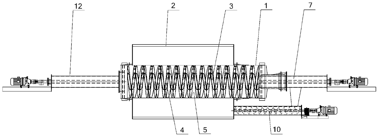
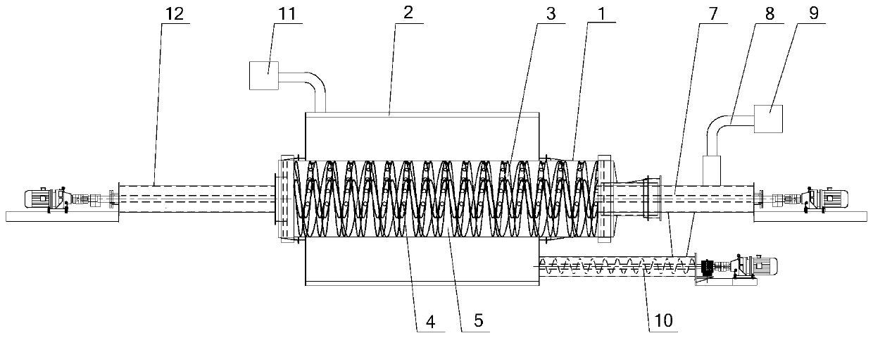
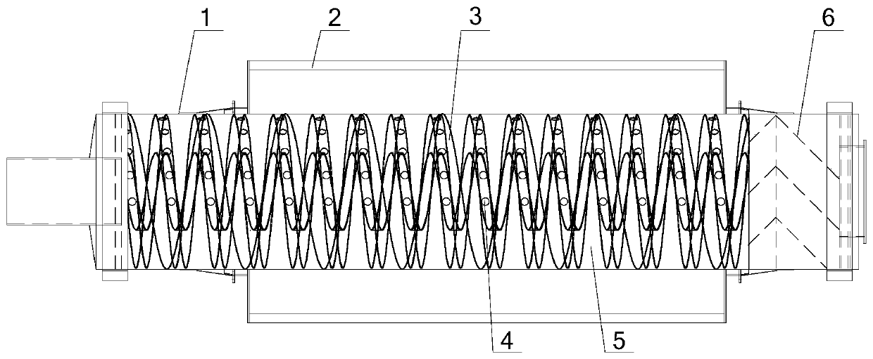
[0029] Please refer to Figure 1-Figure 6 , the embodiment of the present invention provides a kind of pyrolysis equipment, comprises cracking tube 1 and combustion tube 2, and combustion tube 2 is sheathed in the outer periphery of cracking tube 1, and cracking tube 1 rotates relative to fixed combustion tube 2;


PUM


Abstract

The invention discloses cracking equipment, which comprises a cracking cylinder and a combustion cylinder, wherein the combustion cylinder is hermetically sleeved on the periphery of the cracking cylinder, and the cracking cylinder rotates oppositely to the combustion cylinder arranged fixedly; the cracking equipment further comprises a gas communication cavity arranged in the cracking cylinder and separated from the interior of the cracking cylinder, the gas communication cavity communicates with the combustion cylinder so that the heating gas of the combustion cylinder is introduced into thegas communication cavity, and the cavity body wall of the gas communication cavity is used for transferring heat to the material in the cracking cylinder; the solid waste cracked in the cracking cylinder is conveyed into the combustion cylinder through a material return conveyor. The heating gas of the combustion cylinder provided by the application is introduced into the gas communication cavity, and the cavity body wall of the gas communication cavity greatly increases the heat transferring area in the cracking cylinder, so that the material can be in contact heat transferring with the cavity body wall of the gas communication cavity and the inner cylinder wall of the cracking cylinder at the same time, and the heat transferring efficiency is improved. In addition, the solid waste in the cracking cylinder is conveyed into the combustion cylinder for combustion by the material return conveyor, and the resource waste is reduced.

Description


Claims


Application Information

Patent Timeline
Owner ZHAOYUAN HUICHAO NEW ENERGY TECH CO LTD
Why Eureka
Try Eureka