Valve rod of acting valve

A technology of actuating valve and valve stem, which is applied in the direction of lift valve, valve device, engine components, etc., can solve the problems of high processing difficulty, complex valve stem structure, unstable action time, etc., and achieves low design difficulty, simple structure, Easy to process effects

Pending Publication Date: 2018-06-29
XIANGYANG HANGLI ELECTROMECHANICAL TECH DEV
View PDF0 Cites 0 Cited by
  • Summary
  • Abstract
  • Description
  • Claims
  • Application Information

AI Technical Summary

Problems solved by technology

Such a valve stem has a complex structure and is difficult to process, and the fluid flowing near the blades cannot completely

Method used


Image

  • Valve rod of acting valve
  • Valve rod of acting valve
  • Valve rod of acting valve

Examples


Example Embodiment

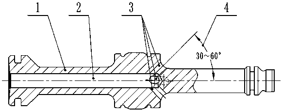
[0018] In the following description, the clockwise and counterclockwise rotations are viewed from left to right.

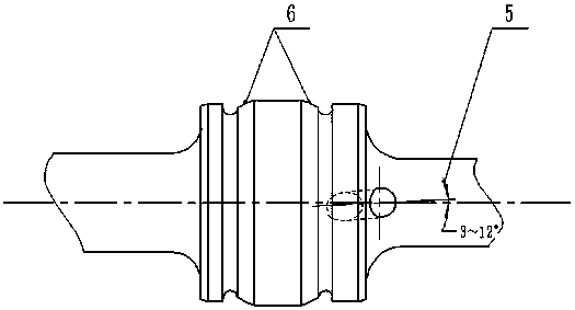
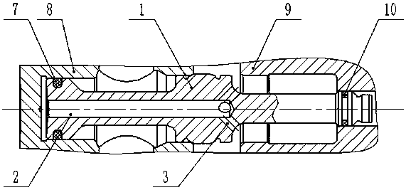
[0019] figure 1 , 2 In the center position of one end of the valve stem body 1, a deep hole coaxial with the valve stem is opened as the oil passage 2, and its outlet is 4 compound angle oil holes 3. The 4 compound angle oil holes 3 should be uniformly distributed in the axial direction. The total cross-sectional area should be approximately equal to the cross-sectional area of ​​the oil passage. The axis of a single composite hole should form an angle -4 with the axis of the oil passage in the Y direction, and the angle -4 should be 30°-60°, and intersect at a point on the axis of the oil passage. The axis of the oil passage should be at the axis of the oil passage. There is an included angle of 2 in the X direction, which should be 3°-12°. The valve stem body 1 has a sealing surface, and the sealing surface is a spherical sealing surface 6 for sealing with the valve


PUM


Abstract

A valve rod of an acting valve comprises a valve rod body, one end face of the valve rod body is provided with an oil duct in the axial direction, two or more combined angle oil-passing holes communicating with the outside are connected to an outlet of the oil duct, a first included angle is formed between the axes of the combined angle oil-passing holes and the axis of the oil duct in the Y direction, and a second included angle is formed between the axes of the combined angle oil-passing holes and the axis of the oil duct in the X direction. When the acting valve performs the separating/combining action, the valve rod body moves in the axial direction under the differential pressure action, fluid passes through the combined angle oil-passing holes under the action of pressure, angular component force is generated for the valve rod body, and then the valve rod body can move forwards spirally. Meanwhile, the fluid passing through the combined angle oil-passing holes forms a vortex, andturbulence is avoided. The speed and stability of the axial motion process of the valve rod body can be improved under the combined action of rotation of the valve rod body and the fluid vortex. Onlythe non-fit dimension of the valve rod body is changed, neither the assembly relation nor other components are affected, and the valve rod of the acting valve is small in design difficulty, simple instructure, easy to machine and free of maintenance.

Description


Claims


Application Information

Patent Timeline
Owner XIANGYANG HANGLI ELECTROMECHANICAL TECH DEV
Why Eureka
Try Eureka