Stamping part surface grinding device for refrigerator production

A technology for stamping parts and refrigerators, which is applied in the field of surface grinding devices for stamping parts used in refrigerator production. It can solve the problems of easily injuring workers, affecting work efficiency, increasing work intensity, etc., and achieves the effects of improving grinding efficiency, convenient operation, and avoiding accidental injuries.

Inactive Publication Date: 2018-08-28
合肥光华机械有限公司
View PDF0 Cites 1 Cited by
  • Summary
  • Abstract
  • Description
  • Claims
  • Application Information

AI Technical Summary

Benefits of technology

This patented technology allows for efficient polishings of stampged part surfaces used in manufacturing processes like refrigraphy or printing presses while reducing human error risk during these operations. It achieves this through moving the polizer along horizontally and controllably pushing/pullring it back onto its own conveyor belt system that moves them around freely within an enclosed area called the machine's box. A turnover mechanism then turns the steering plates and materials into receivers at opposite ends of the machine. These devices allow for easy handling and rotation of the stamper before transferring it to another location where they can be further processed. Overall, this technology simplifies the process of producing high-quality products from cold rolled steel sheets.

Problems solved by technology

The technical problem addressed in this patented text relating to producing these types of punchings from stamps made up of materials like metal sheet that can easily become bent during their manufacturing processes due to factors like heat stress caused by friction between them and pressure applied through pressing tools. This causes damage over time which makes maintenance difficult and reduces productivity.

Method used


Image

  • Stamping part surface grinding device for refrigerator production
  • Stamping part surface grinding device for refrigerator production

Examples


Embodiment Construction

[0017] In order to clearly understand the technical solution of the present invention, its detailed structure will be presented in the following description. It is apparent that the implementation of the embodiments of the invention is not limited to specific details familiar to those skilled in the art. The preferred embodiments of the present invention are described in detail below, and there may be other implementations besides those described in detail.

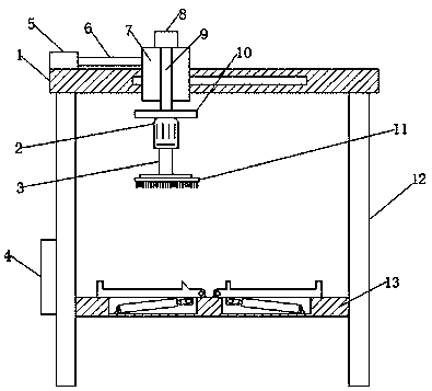
[0018] As shown in the figure, a surface grinding device for stamping parts used in refrigerator production according to the present invention includes a crossbeam 1, a chute is arranged inside the crossbeam 1, and a slider 7 is installed on the outside of the crossbeam 1, and the slider 7 is slidably connected with the chute, a first drive cylinder 5 is installed on one side of the upper surface of the crossbeam 1, and a first telescopic rod 6 is installed on the output end of the first drive cylinder 5, and the other end o


PUM


Abstract

The invention belongs to the technical field of refrigerator production devices, and particularly relates to a stamping part surface grinding device for refrigerator production. The device comprises across beam, a sliding groove is formed in the cross beam, a sliding block is arranged on the outer side of the cross beam, the sliding block is in sliding connection with the sliding groove, a firstdrive air cylinder is arranged on one side of the upper surface of the cross beam, the output end of the first drive air cylinder is provided with a first telescopic rod, the other end of the first telescopic rod is fixedly connected with the sliding block, a through hole is formed in the sliding block, a second telescopic rod is arranged in the through hole, a second drive air cylinder is arranged at one end of the second telescopic rod, a mounting block is arranged at the other end of the second telescopic rod, a drive motor is fixedly arranged on the bottom of the mounting block, and the output end of the drive motor is provided with a rotating shaft. Shortcomings in the prior art are overcome, the structure is simple, operation is convenient, two faces of a stamping part are ground, manual turning over of the stamping part is avoided, time and labor are saved, personal safety is ensured, and unnecessary injuries are avoided.

Description


Claims


Application Information

Patent Timeline
Owner 合肥光华机械有限公司
Why Eureka
Try Eureka