Power line connection protection structure, gateway and power line connection method for gateway

A technology for protecting structures and power wiring, applied in network connections, clamping/spring connections, electrical components, etc., can solve problems such as unimaginable consequences, power cord drop, and wiring board damage, so as to improve safety and improve installation efficiency Effect

Inactive Publication Date: 2018-09-07
GREE ELECTRIC APPLIANCES INC
View PDF5 Cites 2 Cited by
  • Summary
  • Abstract
  • Description
  • Claims
  • Application Information

AI Technical Summary

Benefits of technology

The present in this new design improves how well an access device's gateway has its own protective circuitry that makes sure everything stays secure during operation by preventing unauthorized users from accessing sensitive data or services through these devices. This improvement allows for better control over their network while still being able to communicate properly.

Problems solved by technology

The technical problem addressed in this patented text relates how to protect electrical components from being damaged by external factors like dirt particles that may get inside through holes made during manufacturing processes when connecting cables between different parts within an electronics device (such as switches).

Method used


Image

  • Power line connection protection structure, gateway and power line connection method for gateway
  • Power line connection protection structure, gateway and power line connection method for gateway
  • Power line connection protection structure, gateway and power line connection method for gateway

Examples


Embodiment Construction

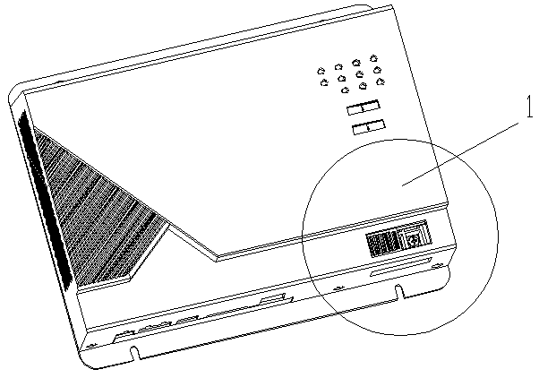
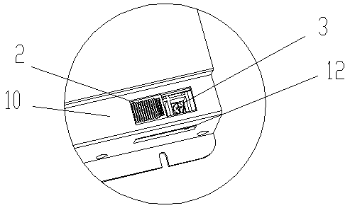
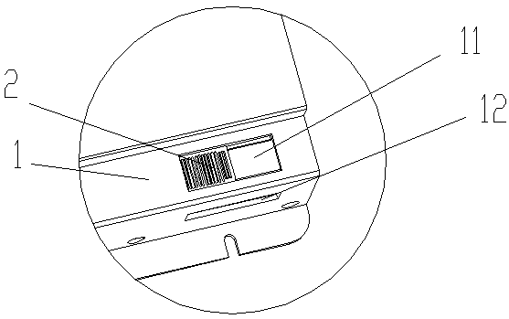
[0023] Such as Figure 1 to Figure 3 As shown, the power wiring protection structure proposed by the present invention includes: a housing 1 and a wiring board 3, the wiring board 3 is installed in the housing 1, the upper cover 10 of the housing 1 is provided with a wiring installation opening 11, and the wiring installation opening 11 Rectangular, set at the position facing the wiring board 3, so that the wiring screws on the wiring board 3 can be disassembled at the wiring installation opening 11, and the wiring installation opening 11 is provided with a movable cover plate 2 connected by a connector , the opening can be opened or closed through the cover plate 2. There is a wiring hole 12 corresponding to the wiring board on one side of the housing 1, which is used as the wiring port of the power line. When using, open the cover plate 2, and then use a screwdriver to gently Lift the screw on the wiring board 3 a little, then put the power cord from the side of the wiring hole


PUM


Abstract

The invention discloses a power line connection protection structure, a gateway and a power line connection method for the gateway. The power line connection protection structure comprises a shell anda wiring board, wherein the wiring board is installed in the shell; the side wall of the shell is provided with a wiring hole used for inserting a wire in a position corresponding to the wiring board; a wiring installation opening is arranged in the position, corresponding to the wiring board, of the upper cover of the shell; a movable cover plate is arranged at the opening of the wiring installation opening; and the cover plate is connected to the shell through a connecting piece. The wiring board is installed inside the shell, and the corresponding installation opening is arranged in the shell, so that the safety of the gateway is improved.

Description


Claims


Application Information

Patent Timeline
Owner GREE ELECTRIC APPLIANCES INC
Why Eureka
Try Eureka