Auxiliary device for punching plate

A technology for auxiliary devices and plates, which is applied to workbenches, manufacturing tools, etc., can solve the problems of high labor costs, personnel injuries, heavy plates, etc., and achieve the effect of saving labor costs and increasing the safety factor

Inactive Publication Date: 2018-11-27
合肥翔威机电科技有限公司
View PDF0 Cites 0 Cited by
  • Summary
  • Abstract
  • Description
  • Claims
  • Application Information

AI Technical Summary

Problems solved by technology

[0002] At present, it is necessary to punch holes in the plates in mechanical manufacturing. However, some plates are relatively large, so it is very difficult to manually turn over and turn the plates. The specific defects are as follows: 1. The plates are relatively heavy and require several people. Coordinated handling, high labor costs; 2. In the process of moving plates, there are many risk factors, which are easy to cause injury to personnel

Method used


Image

  • Auxiliary device for punching plate

Examples


Embodiment Construction

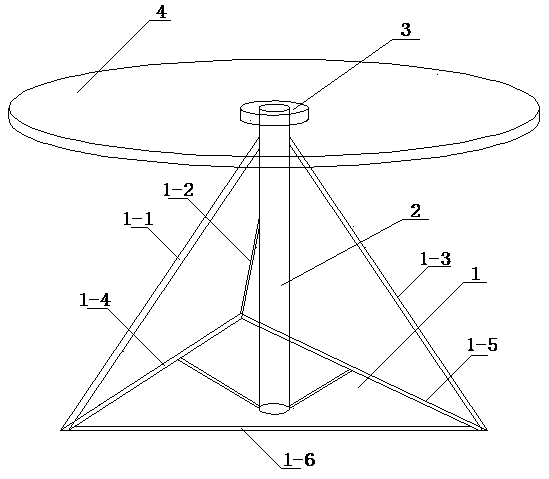
[0009] refer to figure 1 , an auxiliary device for plate punching, which includes a steel triangle seat 1, a ball bearing mounting column 2, a ball bearing 3 and a disc 4, and the steel structure triangle seat 1 includes a first steel bar 1-1, a second The second steel bar 1-2, the third steel bar 1-3, the fourth steel bar 1-4, the fifth steel bar 1-5, the sixth steel bar 1-6, the fourth steel bar 1-4, the fifth steel bar Bar 1-5 and the sixth steel bar 1-6 are connected end to end to form the bottom surface of the steel structure triangular seat, the bottom of the first steel bar 1-1, the second steel bar 1-2, and the third steel bar 1-3 are connected The bottom surface of the triangular seat is connected, the upper end is connected with the upper end of the ball bearing installation column 2, the bottom end of the ball bearing installation column 2 is fixed on the fourth steel bar 1-4 and the fifth steel bar 1-5 through strip steel, and the ball bearing 3 is installed At th...


PUM


Abstract

An auxiliary device for punching a plate relates to the technical field of machine manufacturing. The device is characterized by comprising a steel structure triangular seat, a ball bearing mounting column, a ball bearing and a disc, wherein the steel structure triangular seat comprises a first steel bar, a second steel bar, a third steel bar, a fourth steel bar, a fifth steel bar and a sixth steel bar, the fourth steel bar, the fifth steel bar and the third steel bar are connected from the front to end to form the bottom surface of the steel structure triangular base, the bottom end of the first steel bar, second steel bar and third steel bar are connected with the bottom surface of the steel structure triangular base, the upper end is connected with the upper end of the ball bearing mounting column, the bottom end of the ball bearing mounting post is fixed on the fourth steel bar and the fifth steel bar through a strip-shaped steel; the ball bearing is arranged at the top end of theball bearing mounting column; and the disc is arranged on the ball bearing. The device has the advantages of simple structure, convenience and practicability, labor cost saving and increasing work safety coefficient and the like.

Description


Claims


Application Information

Patent Timeline
IPC IPC(8): B25H1/14
CPCB25H1/14
Inventor 张霖
Owner 合肥翔威机电科技有限公司
Why Eureka
Try Eureka