Paint stirring device for production of color coated plates and with no sticking to walls
A technology of stirring device and color-coated plate, which is applied to mixers with rotary stirring devices, accessories of mixers, transportation and packaging, etc., can solve problems such as cleaning difficulties and paint adhesion, save raw materials, reduce hazards, and facilitate cleaning. Effect
- Summary
- Abstract
- Description
- Claims
- Application Information
AI Technical Summary
Problems solved by technology
Method used
Image

Examples
Example Embodiment
[0020] Example 1
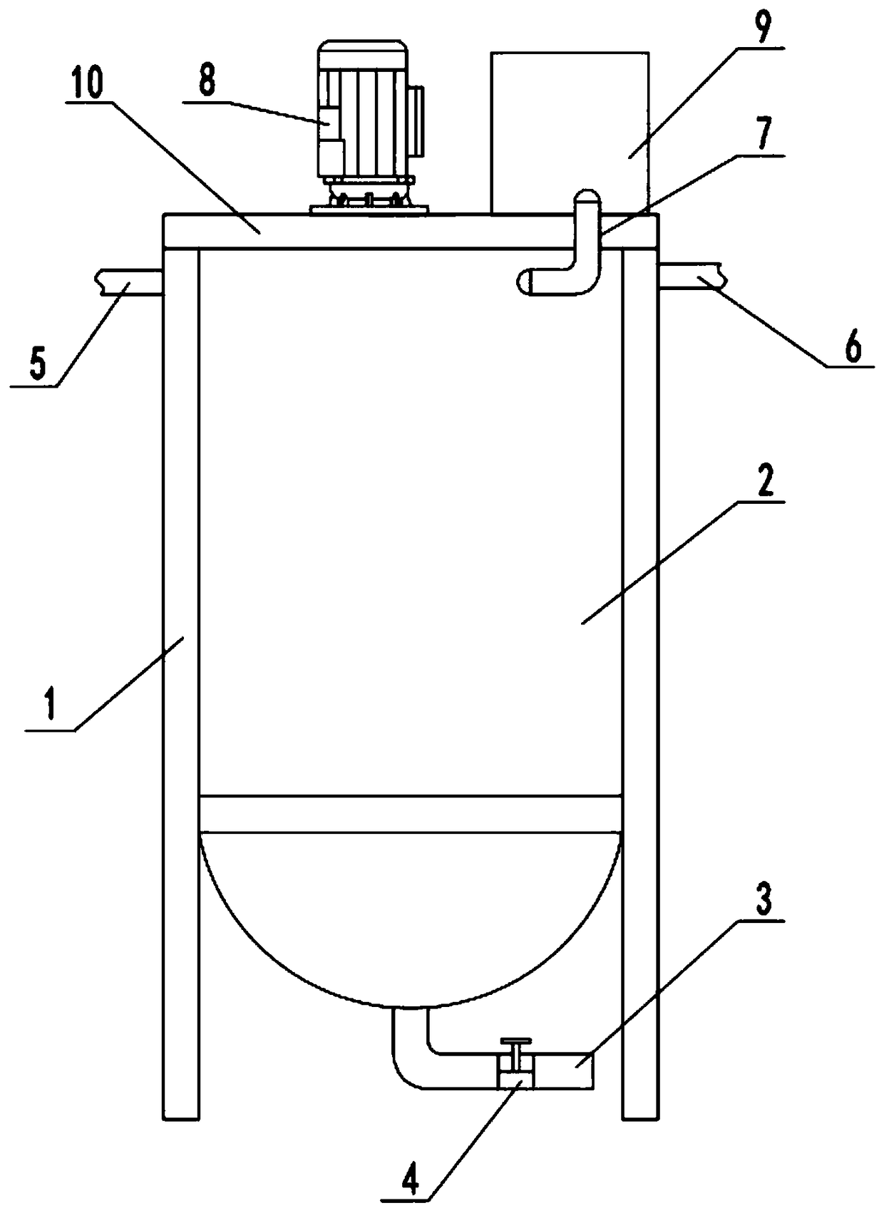
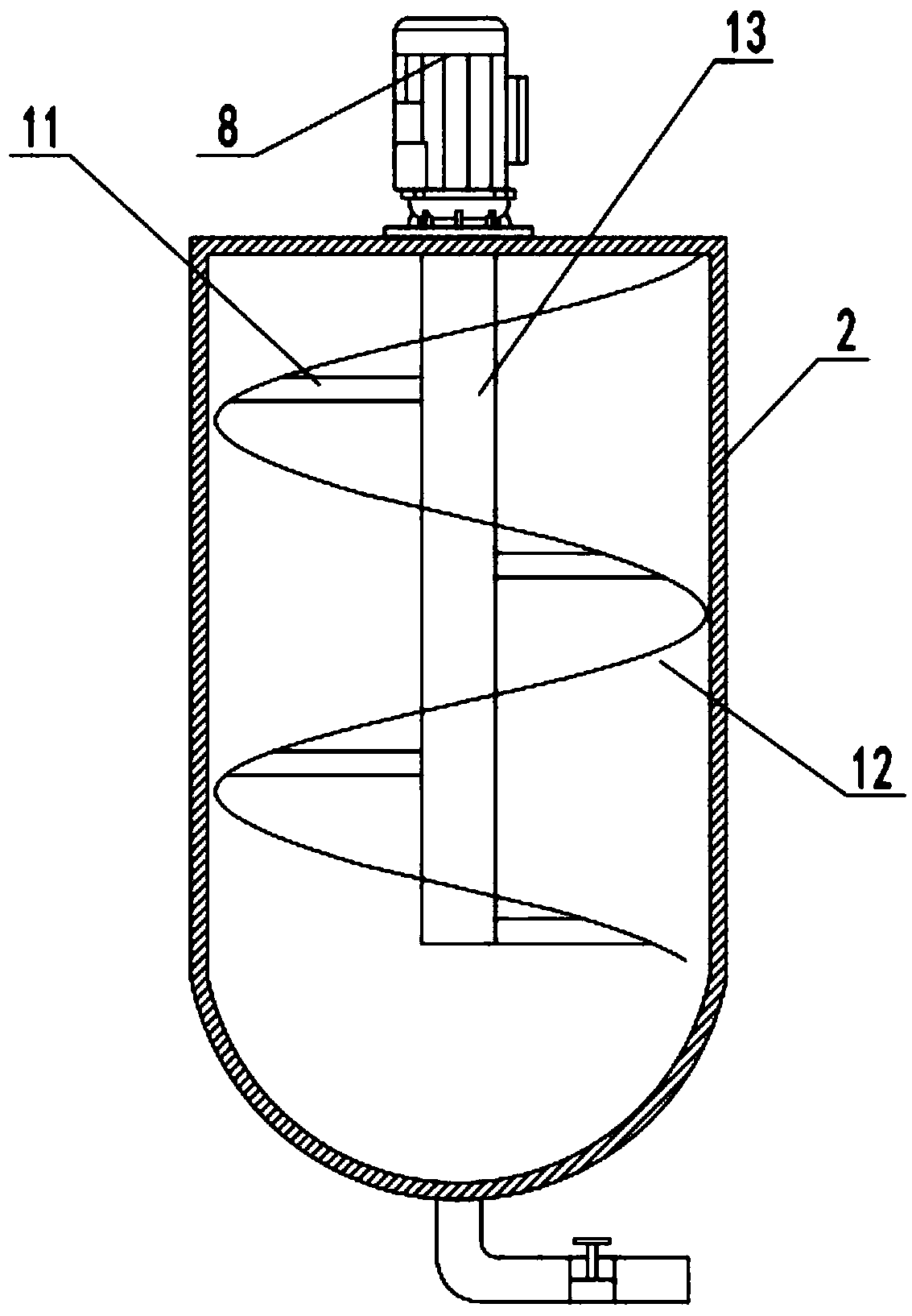
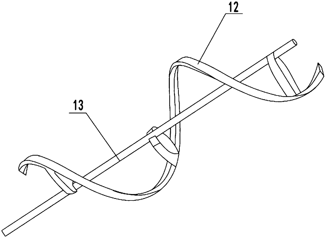
[0021] See Figure 1~3 In the embodiment of the present invention, a non-stick paint mixing device for color-coated board production includes a frame 1, a mixing tank 2 and a mixing motor 8. A cylindrical mixing tank 2 is installed in the frame 1. The top of the stirring tank 2 is connected with a feeding pipe 5 and a liquid feeding pipe 6. The feeding pipe 5 and the liquid feeding pipe 6 are used to input the solute and solvent into the stirring tank 2, where the feeding pipe 5 is installed on the vacuum At the output end of the feeder, a top plate 10 is fixed on the top of the frame 1, and a stirring motor 8 is installed on the top plate 10. The output end of the stirring motor 8 is connected to the rotating shaft 13 placed in the mixing tank 2, and the outside of the rotating shaft 13 The connecting rod 11 is connected with the spiral bar 12. The rotating shaft 13, the connecting rod 11 and the spiral bar 12 are made of stainless steel, which is corrosion resi
Example Embodiment
[0023] Example 2
[0024] See Figure 4 When the mixing tank 2 is working, the paint raw materials will produce some harmful volatile gases, which will cause harm to the environment and nearby operators. Therefore, in this embodiment, an exhaust gas treatment box 9 is installed on the top plate 10 9 is connected to the top of the mixing tank 2 through an exhaust pipe 7.
[0025] Further, the processing box 9 includes a casing 901 and an exhaust pipe 902, a fan 903, and an activated carbon pipe 905 in the casing 901. The exhaust pipe 902 is connected to the exhaust pipe 7, and the exhaust pipe 902 is installed There is a fan 903, and the exhaust pipe 902 is connected to the activated carbon pipe 905 through the connecting pipe 904. The activated carbon pipe 905 is filled with porous activated carbon, which can adsorb the exhaust gas. The activated carbon pipe 905 is connected to the exhaust pipe 908. After the exhaust gas is adsorbed, It is discharged from the air outlet 908.
[0026]
PUM
 Abstract
Description
Claims
Application Information
 - R&D Engineer
- R&D Manager
- IP Professional
- Industry Leading Data Capabilities
- Powerful AI technology
- Patent DNA Extraction
Browse by: Latest US Patents, China's latest patents, Technical Efficacy Thesaurus, Application Domain, Technology Topic.
© 2024 PatSnap. All rights reserved.Legal|Privacy policy|Modern Slavery Act Transparency Statement|Sitemap