IMPLICATION logic gate
A technology of logic gate and logic input, which is applied in the field of nanometers, can solve problems such as difficulty in the application of logic gates, and achieve the effects of strong anti-interference ability, stable and correct output, and high stability
- Summary
- Abstract
- Description
- Claims
- Application Information
AI Technical Summary
Benefits of technology
Problems solved by technology
Method used
Image

Examples
Embodiment 1
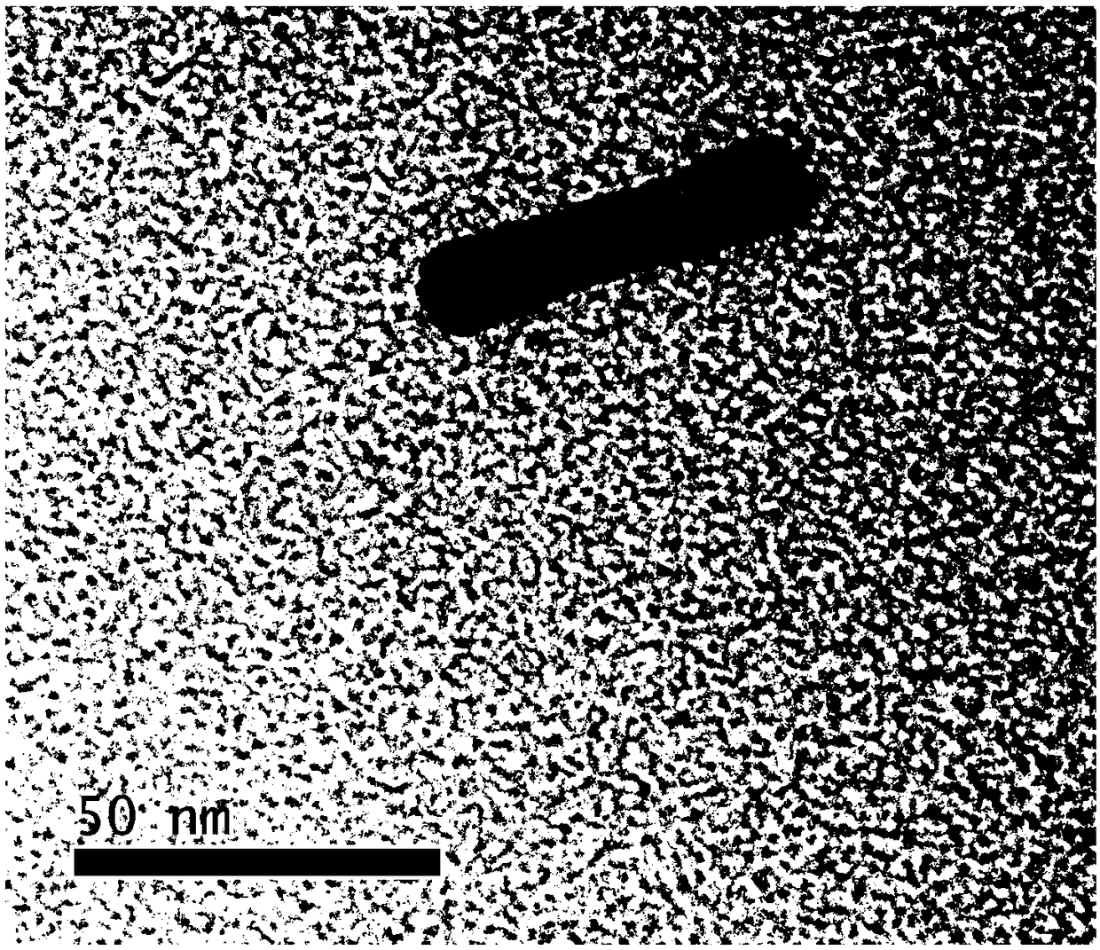
[0041] In this example, the synthesis and characterization of gold nanorods are carried out.
[0042] 1.1 Synthesis of gold species: Add 5mL 0.1mol / L CTAB and 25μL 50mmol / L chloroauric acid into a 25mL flask, stir the mixture for 5min, add 300μL 10mmol / L freshly prepared sodium borohydride solution to the mixture, and stir for 25s , the color of the solution turns from brown to brown, indicating the formation of gold species, and the prepared gold species solution is stored in an environment of 27-30° C. for later use.
[0043] 1.2 Preparation of growth solution: Add 200 μL of 1mol / L hydrochloric acid and 100 μL of 50 mmol / L chloroauric acid into 10 mL of 0.1 mol / L CTAB solution, stir for 5 minutes, and then mix 120 μL of 10 mmol / L silver nitrate solution and 100 μL of 100 mmol / L The ascorbic acid solution is sequentially added to the above mixture, and the growth liquid is obtained after mixing evenly.
[0044] 1.3 Preparation of gold nanorods: inject 24 μL of t
Embodiment 2
[0048] This embodiment provides the input / output characteristics of the IMPLICATION logic gate constructed by the present invention.
[0049] The gold nanorods synthesized in Example 1 were used.
[0050] The etching solution contains 200mmol / L hydrogen peroxide, 0.4mmol / L sodium iodide, and 0.4mmol / L hydrochloric acid.
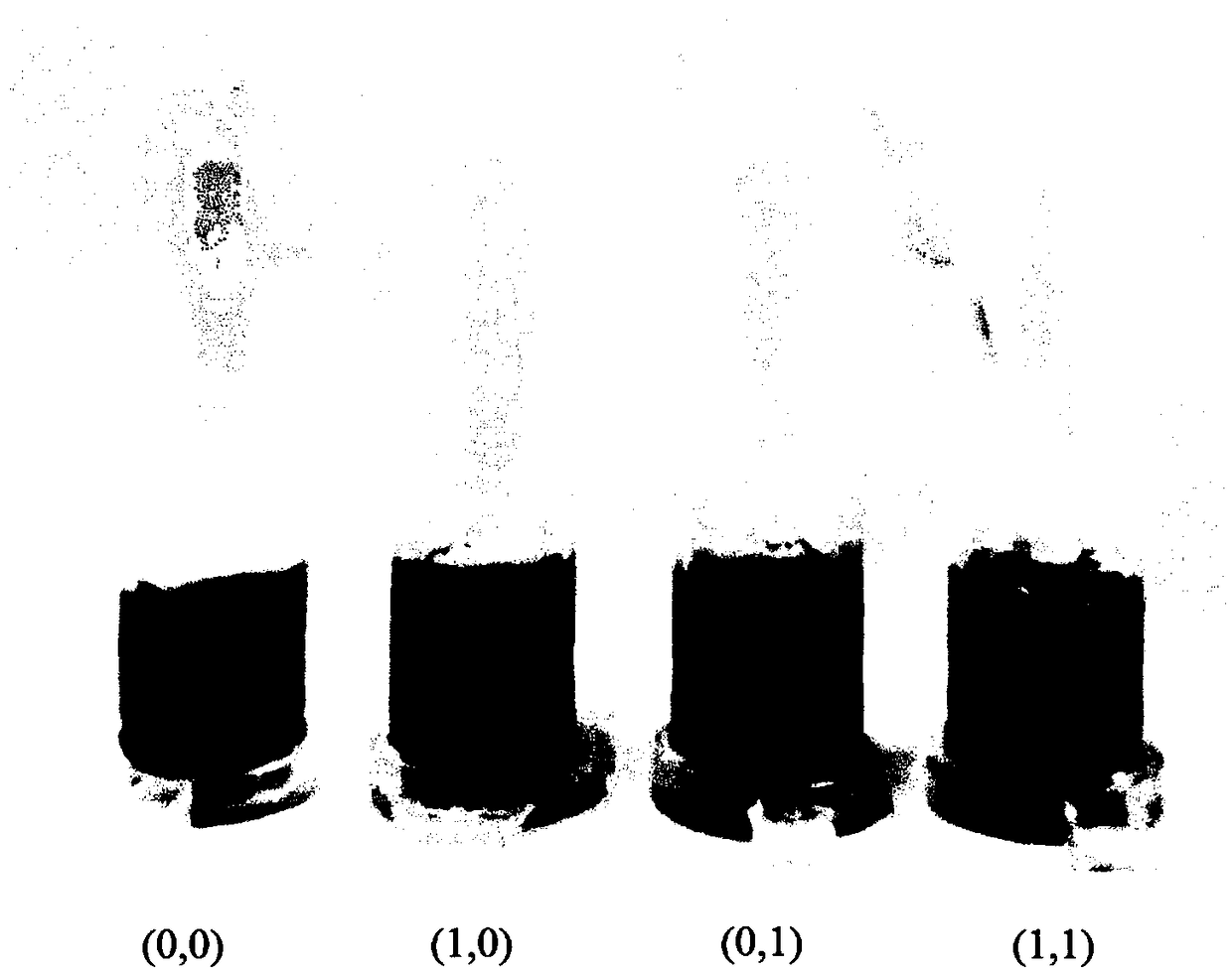
[0051] The first logic input is 15μL 0.8μmol / L Hg 2+ , the second logic input is 15μL 0.8mmol / L Cu 2+ .
[0052] When there is an input signal, it is defined as 1; when it does not contain an input signal, it is defined as 0. The four input signal forms are: neither adding 15μL 0.8μmol / L Hg 2+ Without adding 15μL 0.8mmol / L Cu 2+ , defined as (0,0); without adding 15 μL 0.8 μmol / L Hg 2+ But add 15μL 0.8mmol / L Cu 2+ , defined as (0,1); add 15μL 0.8μmol / LHg 2+ But do not add 15μL 0.8mmol / L Cu 2+ , defined as (1,0); adding 15μL 0.8μmol / L Hg 2+ Then add 15μL 0.8mmol / L Cu 2+ , defined as (1,1).
[0053] 2.1 The output characteri
Embodiment 3
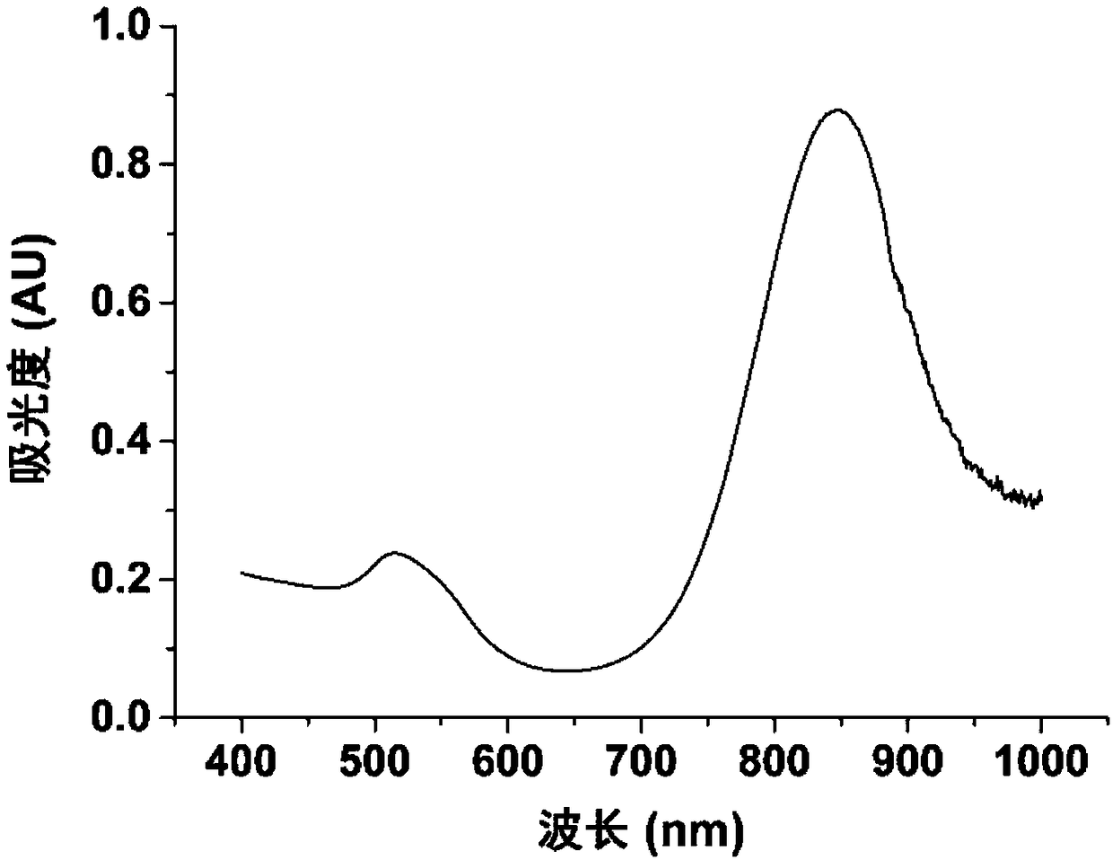
[0062] Three batches of gold nanorod working solutions were synthesized using the method of Example 1, and logic gates were constructed using the method parameters and steps of Example 2, and three parallel experiments were performed on each batch of gold nanorod working solutions. The final solution L-LSPR wavelength blue shift value Δλ calculated by spectral measurement is as follows Figure 5As shown, when the input is (1,0), the color of the final solution does not change visually, it is red, and the results of nine spectral measurements show that the wavelength blue shift value Δλ of the final solution is 1.6nm, and the standard deviation is 0.6nm; when the input When it is (0,0), (0,1) and (1,1), the gold nanoparticles are not protected, and etching has occurred, and the final color of the solution is blue visually, and the average values of Δλ measured in nine times are respectively At 201.5nm, 204.1nm and 194.6nm, the standard deviations of the blue shift values are 6
PUM
| Property | Measurement | Unit |
|---|---|---|
| Concentration | aaaaa | aaaaa |
| Length | aaaaa | aaaaa |
| Diameter | aaaaa | aaaaa |
Abstract
Description
Claims
Application Information
 - R&D Engineer
- R&D Manager
- IP Professional
- Industry Leading Data Capabilities
- Powerful AI technology
- Patent DNA Extraction
Browse by: Latest US Patents, China's latest patents, Technical Efficacy Thesaurus, Application Domain, Technology Topic.
© 2024 PatSnap. All rights reserved.Legal|Privacy policy|Modern Slavery Act Transparency Statement|Sitemap