Conveyor belt forced positioning device for belt conveyor

A belt conveyor and positioning device technology, applied in the direction of conveyor control devices, conveyors, conveyor objects, etc., can solve the problems of conveyor belt damage, support frame deformation, loss, etc., to achieve convenient installation and maintenance, and avoid damage , cheap effect

Pending Publication Date: 2019-01-11
CHINA TOBACCO HENAN IND
View PDF0 Cites 0 Cited by
  • Summary
  • Abstract
  • Description
  • Claims
  • Application Information

AI Technical Summary

Benefits of technology

This technology helps prevent damage caused by misalignment or shifting during transportation due to improper placement of components such as guides for conveying materials like paper sheets. When there are slight changes in direction (such as if an object falls onto one end), this system automatically adjusts its location based upon these differences. If any issues with alignment occur quickly enough, the lights will trigger their own mechanism to activate them before they go too far towards other parts of the machine. Once triggered, the systems send signals through wires connected to sensors inside the machines' control panel. These signals then cause alarms to sound at predeteriorating times.

Problems solved by technology

This patented technical problem addressed during this process involves unexpected failure or malfunctions that can lead to rapid changes on the machine's drive system due to factors like vibrations caused by uneven surfaces inside the supporting structure (the device).

Method used


Image

  • Conveyor belt forced positioning device for belt conveyor
  • Conveyor belt forced positioning device for belt conveyor
  • Conveyor belt forced positioning device for belt conveyor

Examples


Embodiment Construction

[0030] The specific implementation manners of the present invention will be described in detail below in conjunction with the accompanying drawings.

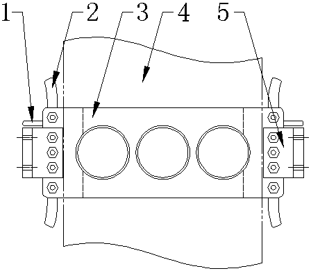
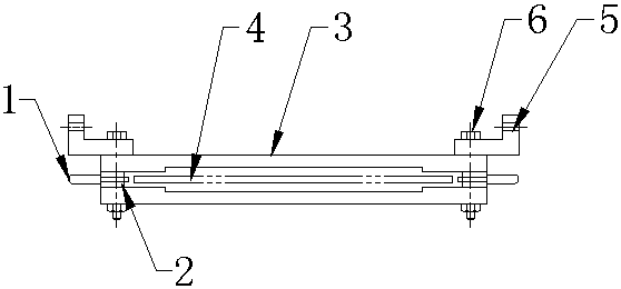
[0031] Such as Figure 1 to Figure 9 As shown, a conveyor belt forced positioning device for a belt conveyor of the present invention includes a conveyor belt guide structure and a positioning warning structure 1. The conveyor belt guide structure includes guide plates 3 arranged oppositely on the upper and lower sides of the conveyor belt 4 and on the conveyor belt. The side guide rails 2 arranged opposite to each other on the left and right sides of the conveyor belt, the two guide plates 3 and the guide rails 2 on both sides are surrounded to form a conveyor belt guide channel, and the conveyor belt 4 passes through the conveyor belt guide channel.

[0032] In this embodiment, the guide plate 3 is also fixedly connected with a positioning plate 5, the positioning plate 5 is an L-shaped plate structure formed by fixed connection


PUM


Abstract

The invention discloses a conveyor belt forced positioning device for a belt conveyor. The conveyor belt forced positioning device comprises a conveyor belt guiding structure and positioning warning structures, the conveyor belt guiding structure comprises guiding plates oppositely arranged on the upper and lower sides of a conveyor belt and side guide rails oppositely arranged on the left and right sides of the conveyor belt, and a conveyor belt guiding channel is defined among the two guiding plates and the two side guide rails; the positioning warning structures are installed at the positions of the side guide rails, and each include a casing, a warning light, a detecting rod and a detecting rod resetting device, wherein a columnar installation space is arranged inside the casing, the warning light is located at one end of the columnar installation space, the detecting rod penetrates out of the other end of the columnar installation space in a sliding manner, and the side, close tothe detecting rod, of the warning light is provided with a spring contact; when the conveyor belt deflects towards the left or the right and exceeds the preset position, the conveyor belt pushes the detecting rod on the corresponding side to retract back and trigger the corresponding spring contact, and a circuit of the corresponding warning light is accordingly closed. The conveyor belt forced positioning device can forcibly position the conveyor belt and give out an alarm in the case of equipment failures, and damage to the conveyor belt is avoided.

Description


Claims


Application Information

Patent Timeline
Owner CHINA TOBACCO HENAN IND
Why Eureka
Try Eureka