Dying device

A technology of equipment and dyes, which is applied in solid materials, mixers, types of packaging items, etc., can solve the problems of large quantitative operation error, high labor intensity, low efficiency, etc., and achieves high degree of automation, reduced labor intensity, and simple device structure. Effect

Inactive Publication Date: 2019-01-29
岑浩明
View PDF0 Cites 4 Cited by
  • Summary
  • Abstract
  • Description
  • Claims
  • Application Information

AI Technical Summary

Benefits of technology

This technology allows for precise control over how small colored pigments (dyes) mix with liquid materials like water or other liquids quickly without requiring manual effort. It simplifies the process by allowing it to be done automatically at once instead of manually.

Problems solved by technology

This technical problem addressed by this patented method relates to improving the accuracy and consistency when mixing or adding different types of colorants during manufacturing processes for fabrics such as carpets that require specific colors like reds yellow shades (R). Manual methods have been developed but they still suffer from errors caused by human factors leading to lower productivity rates while also requiring more effort than desired.

Method used


Image

  • Dying device

Examples


Embodiment Construction

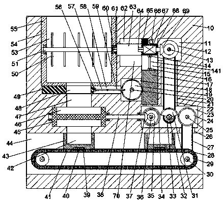
[0015] Such as figure 1 As shown, a kind of dyeing equipment of the present invention includes a body 10, a first installation cavity is arranged in the top end surface of the body 10, a stirring box 55 is fixed in the first installation cavity, and a stirring box 55 is arranged in the stirring box 55. There is a stirring chamber 53 with an upward opening, and the body 10 on the right side of the first installation chamber is provided with a second installation chamber 11, and the first installation chamber and the second installation chamber 11 are communicated with each other. There is a first sliding groove 63, a sliding block 68 is slidably installed in the first sliding groove 63, a driving motor 67 is fixed in the sliding block 68, and a spline shaft 64 is installed on the left side of the driving motor 67, A first bevel gear 69 is installed on the left side of the driving motor 67, and a first rotating shaft 13 is rotatably installed in the front and rear end walls of the


PUM


Abstract

The invention discloses a dying device. The dying device includes a machine body, wherein a first mounting cavity is arranged inside the top end surface of the machine body; a stirring box is fixedlyarranged in the first mounting cavity; the stirring box is provided with a stirring chamber with an upward opening; the portion, at the right side of the first mounting cavity, of the machine body isprovided with a second mounting cavity; a first sliding trough is arranged between the first mounting cavity and the second mounting cavity in a communicating mode; a sliding block is slidably arranged in the first sliding trough; a drive motor is fixedly arranged in the sliding block; the left side of the drive motor is provided with a spline shaft and a first bevel gear in a power mode; a firstrotating shaft is rotatably arranged in the front and rear end walls of the second mounting cavity; and a second bevel gear meshing with the first bevel gear is fixedly arranged on the first rotatingshaft.

Description


Claims


Application Information

Patent Timeline
Owner 岑浩明
Why Eureka
Try Eureka