Counter flow type hot air combustion furnace

A combustion furnace and counter-flow technology, applied in the field of combustion furnaces, can solve the problems of waste gas emission polluting the environment, real-time adjustment of feed amount, insufficient combustion, etc., and achieve the effect of ensuring high efficiency

Inactive Publication Date: 2019-04-05
RES INST OF FORESTRY NEW TECH CHINESE ACAD OF FORESTRY +1
View PDF8 Cites 1 Cited by
  • Summary
  • Abstract
  • Description
  • Claims
  • Application Information

AI Technical Summary

Problems solved by technology

[0003] Aiming at the above-mentioned deficiencies in the prior art, the present invention provides a counter-flow hot air combustion furnace, which effectively solves the problems of insufficient horizontal intake combustion of the combustion furnace, waste gas emission polluting the environment and real-time adjustment of feed quantity

Method used


Image

  • Counter flow type hot air combustion furnace
  • Counter flow type hot air combustion furnace
  • Counter flow type hot air combustion furnace

Examples


Example Embodiment

[0021] The specific embodiments of the present invention will be described in detail below with reference to the accompanying drawings.

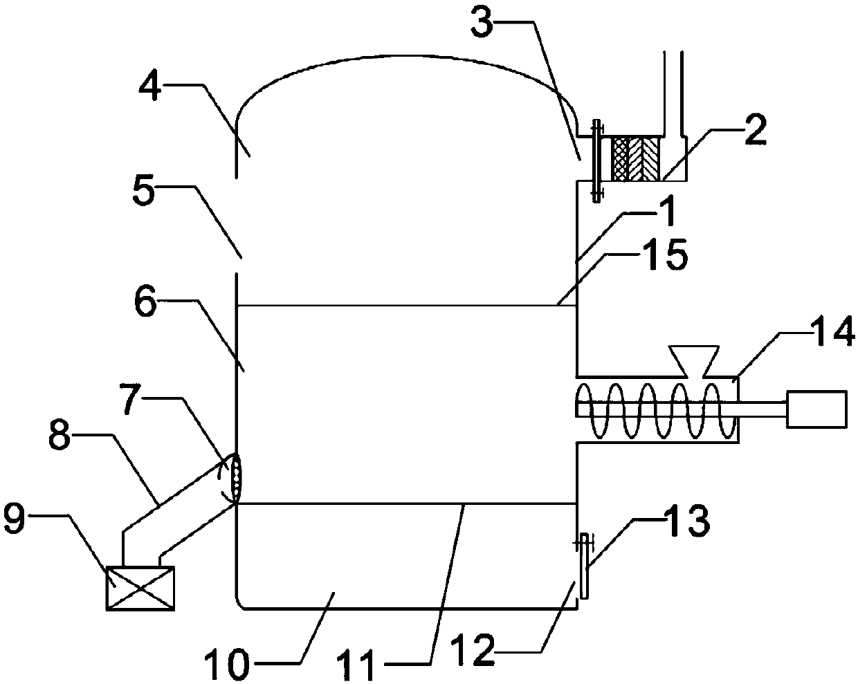
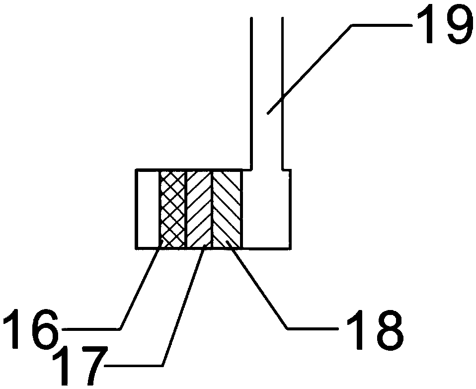
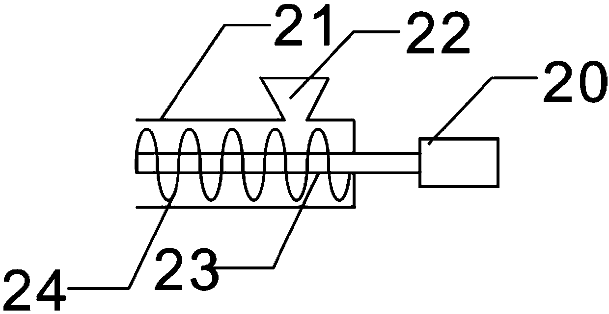
[0022] In an embodiment of the present invention, such as Figure 1-4 As shown, a counter-flow hot-blast combustion furnace is provided, which includes a furnace body 1. A flame stabilizing plate 15 and a burning plate 11 are arranged in the furnace body 1. The flame stabilizing plate 15 and the burning plate 11 sequentially connect the furnace body 1 from top to bottom. It is divided into flame zone 4, combustion zone 6 and slag zone 10. The flame stabilizing plate 15 set above the combustion zone 6 can stabilize the flame and block the dust after combustion to make the flame evenly distributed; the flame zone 4 is set on the left side There is a fire outlet 5, the right side of the flame zone 4 is provided with an air outlet 3, and the air outlet 3 is connected with an air outlet device 2 that can absorb smoke through a flange. Flame or steam is


PUM


Abstract

The invention discloses a counter flow type hot air combustion furnace. The counter flow type hot air combustion furnace comprises a furnace body, wherein a stable flame plate and a combustion plate are arranged in the furnace body, and the furnace body is divided into a flame area, a combustion area and a slag area from top to bottom in sequence; a fire outlet is formed in the left side of the flame area, an air outlet is formed in the right side of the flame area, and the air outlet is connected with an air outlet device for adsorbing smoke through a flange; an air inlet is formed in the left side of the combustion area, and the air inlet is connected with an air blower through an air inlet pipe; the air inlet pipe and the furnace body are at 45 degrees, and a feeding device is arrangedon the right side of the combustion area; the feeding device comprises a feeding pipe, a feeding hopper is arranged on the feeding pipe, a rotating rod is arranged in the feeding pipe, and the rotating rod is connected to the output end of an adjustable motor; and a spiral baffle is arranged on the rotating rod, and a slag opening is formed in the right side of the slag area. The counter flow typehot air combustion furnace effectively solves the problems that the horizontal intake air combustion of the combustion furnace is insufficient, discharging of waste gas pollutes environment and the feed amount is adjusted in real time.

Description


Claims


Application Information

Patent Timeline
Owner RES INST OF FORESTRY NEW TECH CHINESE ACAD OF FORESTRY
Why Eureka
Try Eureka