Application method of novel heat storage heating furnace with reversing control device

A reversing control device and regenerative technology, which are applied in combustion methods, regenerative equipment, and combustion control, etc., can solve the problems that the waste heat of flue gas cannot be used to the maximum extent and cannot be preheated, and are convenient for use and maintenance. Fast, reasonable structure design, high stability effect

Inactive Publication Date: 2017-01-04
苏州云白环境设备股份有限公司
View PDF6 Cites 0 Cited by
  • Summary
  • Abstract
  • Description
  • Claims
  • Application Information

AI Technical Summary

Benefits of technology

This patented technology describes an improvement on existing methods used by renewable energy sources like solar power plants or wind turbines that uses excess thermal energy from their exhaust gases without generating any harmful emissions during operation. These improvements include improving the overall performance of these systems while minimizing environmental impacts caused by traditional fossil fuel combustion processes.

Problems solved by technology

This patented describes an improved type called High Thermal Aware Exchanging Fluoride Gas Technology(HTAF). These techniques involve exchangers between different types of equipment such as boilers or reactors. By doing this they recover excessive thermal power from the flame gases while reducing harmful nitrogen oxides released during burning processes. Additionally, these techniques reduce carbon dioxide emission without increasing overall cost due to increased fossil fuels consumption. Overall, HTCA helps improve greenhouse effectiveness through efficient energy usage.

Method used


Image

  • Application method of novel heat storage heating furnace with reversing control device

Examples


specific Embodiment 1

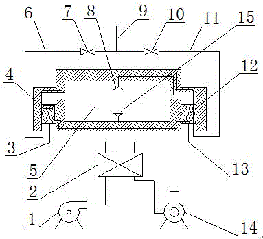
[0013] Specific embodiment one, please refer to figure 1 , a new regenerative heating furnace with a reversing control device, including an air blower 1, a reversing valve 2, a furnace 5, a gas left branch pipe 6, a gas right branch pipe 11 and a flue gas induced draft fan 14, characterized in that: the furnace One end of the 5 is provided with a regenerator 4, the other end of the furnace 5 is provided with a regenerator 12, the middle part of the furnace 5 is provided with a gas upper nozzle 8 and a gas lower nozzle 15, and the gas left branch pipe 6 It is arranged between the gas upper nozzle 8 and the gas main pipe 9, the gas left branch pipe 6 passes through the heat storage body 1 4 and the heat storage body 2 12, and the gas left branch pipe 6 is provided with a valve 1 7, the The gas right branch pipe 11 is arranged between the gas lower nozzle 15 and the gas main pipe 9, the gas right branch pipe 11 passes through the heat storage body 2 12 and the heat storage body 1 4,

specific Embodiment 2

[0017] Specific embodiment two, please refer to figure 1 , the use method of the novel regenerative heating furnace with a reversing control device, comprising an air blower 1, a reversing valve 2, a furnace 5, a gas left branch pipe 6, a gas right branch pipe 11 and a flue gas induced draft fan 14, wherein It is characterized in that its steps are:

[0018] (1) First, it enters the left circulation combustion, and the gas enters the gas left branch pipe 6 from the gas main pipe 9. At this time, the valve 1 7 is opened, and the valve 2 10 is closed at the same time, and the gas passes through the heat storage body 1 4 and the heat storage body 2 12 from the The gas upper nozzle 8 enters the furnace 5; at the same time, the air blower 1 drives the air through the reversing valve 2 to enter the furnace 5 from the pipe 3 through the regenerator 4, and the oxygen in the air and the gas are mixed and burned in the furnace 5, and the combustion The generated flue gas is driven by the


PUM


Abstract

The invention relates to the technical field of heat storage air combustion, in particular to an application method of a novel heat storage heating furnace with a reversing control device. The novel heat storage heating furnace with the reversing control device comprises an air blower, a reversing valve, a hearth, a gas left branch pipe, a gas right branch pipe and a smoke induced draft fan. A heat storage body 1 and a heat storage body 2 are arranged in the novel heat storage heating furnace with the reversing control device. The heat storage body 1 and the heat storage body 2 can alternately absorb heat in smoke, and finally, the heat is transferred to air and gas before entering the hearth, so that the utilization efficiency of the heating furnace to the heat is maximal. The novel heat storage heating furnace with the reversing control device can fully use smoke afterheat without generating secondary pollution, and is higher in stability. In addition, the novel heat storage heating furnace with the reversing control device is reasonable in structural design, convenient and fast in use and maintenance and suitable for popularization and application.

Description


Claims


Application Information

Patent Timeline
Owner 苏州云白环境设备股份有限公司
Why Eureka
Try Eureka