Safe tool replacing method based on tool life application mode
A technology of application mode and tool life, applied in the direction of manufacturing tools, clamping, support, etc., can solve the problems of not considering the processing status of parts, reduce the risk of parts processing quality, etc. Safe and reliable effect of the knife
- Summary
- Abstract
- Description
- Claims
- Application Information
AI Technical Summary
Problems solved by technology
Method used
Image

Examples
Embodiment 1
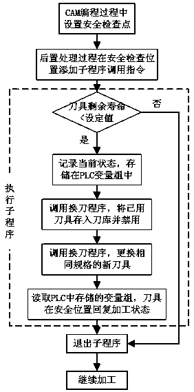
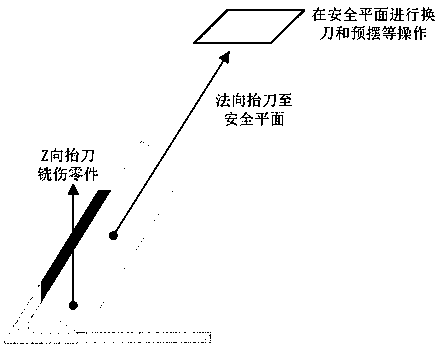
[0027] A safe tool change method based on the tool life application mode in this embodiment, such as figure 1 As shown in the figure, set the safety plane, and perform the tool replacement operation on the safety plane. The tool replacement operation includes recording and saving the current state parameters of the old tool to the PLC variable group, and then replacing the new tool with the new tool, so that the new tool can be restored on the safety plane. Processing state, adjust the new tool to the same working state as the old tool according to the current state parameters.
[0028]When performing programming operations in CAM, establish a safe plane, which is located on the upper part of the parts and tooling, and leave a sufficient safety distance to ensure that the tool will not collide with parts and tooling when performing any swing angle operation after returning to the safe plane. , machine tools, etc. interfere, and then advance and retreat the knife for each operatio
Embodiment 2
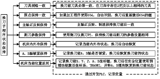
[0030] This embodiment is further optimized on the basis of embodiment 1, such as figure 2 As shown, the current state parameters include tool specification parameters, machining origin coordinate parameters, spindle forward and reverse rotation parameters, tool measurement parameters, machine tool cooling mode parameters, AB axis or AC axis locking state parameters, tool space coordinate parameters, tool Swing angle parameters; read the coordinate values of x, y, z, A, B (or C) before tool change, use the pre-swing function to activate the coordinate system, TRAORI at the safety check position after tool change, and set A, B (or C) C) The swing angle returns to the state before tool change.
[0031] The tool specification parameters include tool information such as tool number; the machining origin coordinate parameters are the preset origin coordinates in the CNC machining space, generally set to X=0, Y=0, Z=0; the spindle forward and reverse parameters are the positive and
Embodiment 3
[0043] This embodiment is further optimized on the basis of the above-mentioned embodiment 1 or 2. After the current state parameters are recorded and saved, the old tool is stored in the tool library of the machine tool and marked as disabled, and then a new tool of the same specification is used.
[0044] After recording and saving the current state parameters of the old tool, the tool change operation can be performed, and the used old tool can be stored in the tool magazine, and then the old tool information can be marked and the old tool can be disabled, because the tool with the same specification is in the The library is marked with the same name, and the used old tool must be set to disable to prevent the used old tool from being used as a new tool when replacing the tool.
[0045] Other parts of this embodiment are the same as those of Embodiment 1 or 2 above, so details are not repeated here.
PUM
 Abstract
Description
Claims
Application Information
 - R&D Engineer
- R&D Manager
- IP Professional
- Industry Leading Data Capabilities
- Powerful AI technology
- Patent DNA Extraction
Browse by: Latest US Patents, China's latest patents, Technical Efficacy Thesaurus, Application Domain, Technology Topic.
© 2024 PatSnap. All rights reserved.Legal|Privacy policy|Modern Slavery Act Transparency Statement|Sitemap