Cable laying device

A technology for laying devices and cables, applied in the direction of cable laying equipment, etc., can solve the problems of rapid cable damage and achieve the effect of improving laying efficiency

Active Publication Date: 2019-04-23
河北盛伟电力工程有限公司
View PDF10 Cites 4 Cited by
  • Summary
  • Abstract
  • Description
  • Claims
  • Application Information

AI Technical Summary

Benefits of technology

This technology allows for efficient cable layings with automatic tools like slitting mechanisms and expanders. Additionally, there may also include features such as adjustable frictional surfaces between roller wheels and lamination layers during operation. These improvements help prevent damage from excess force while ensuring proper placement of wires within the trenches. Overall, this innovation improves the overall performance of cable installations.

Problems solved by technology

In this patented problem addressed by the patents, there were issues related to safely carrying out construction works at different locations within an area while also ensuring proper organization over these materials used throughout their lifespan. These challenged factors led to the development of various methods that aim to improve upon existing systems such as aerial cable placement techniques.

Method used


Image

  • Cable laying device
  • Cable laying device
  • Cable laying device

Examples


Embodiment Construction

[0048] The present invention will be described in further detail below in conjunction with the accompanying drawings.

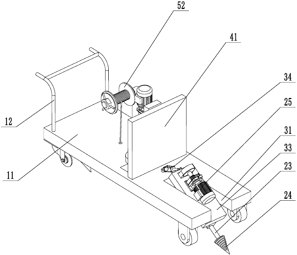
[0049] refer to figure 1 , is a cable laying device disclosed in the present invention, including a slotting mechanism, an expansion mechanism, a laying mechanism and a back-embedding mechanism. These four parts are all installed on the mobile base 11. Platform and four walking wheels installed on the bottom surface of the workbench, one side of the mobile base 11 is welded with handrails 12, which is convenient for the staff to promote.

[0050] For the convenience of description, the side on which the handrail 12 is welded on the mobile base 11 is called the rear side, and the side opposite to this side is called the front side.

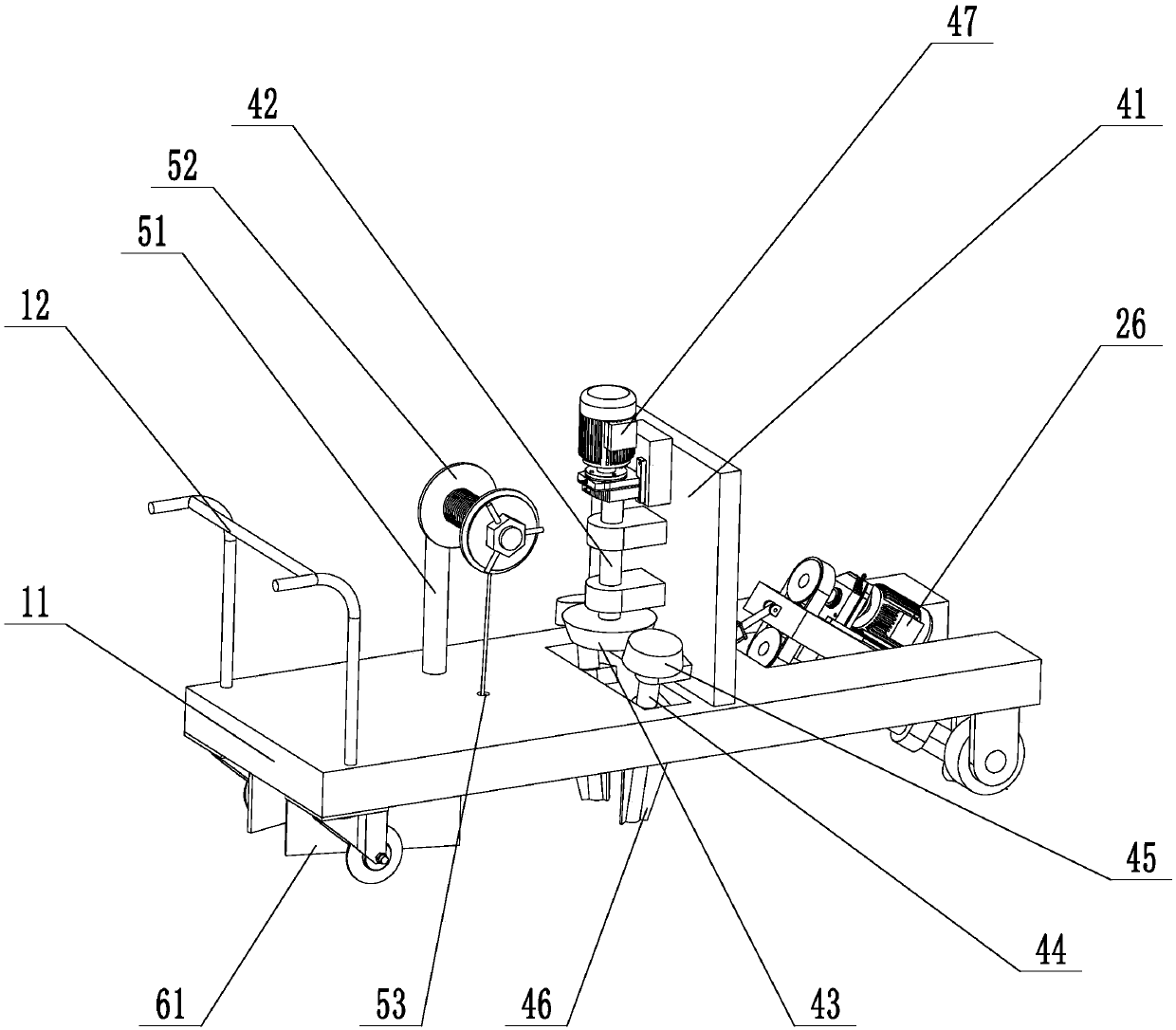
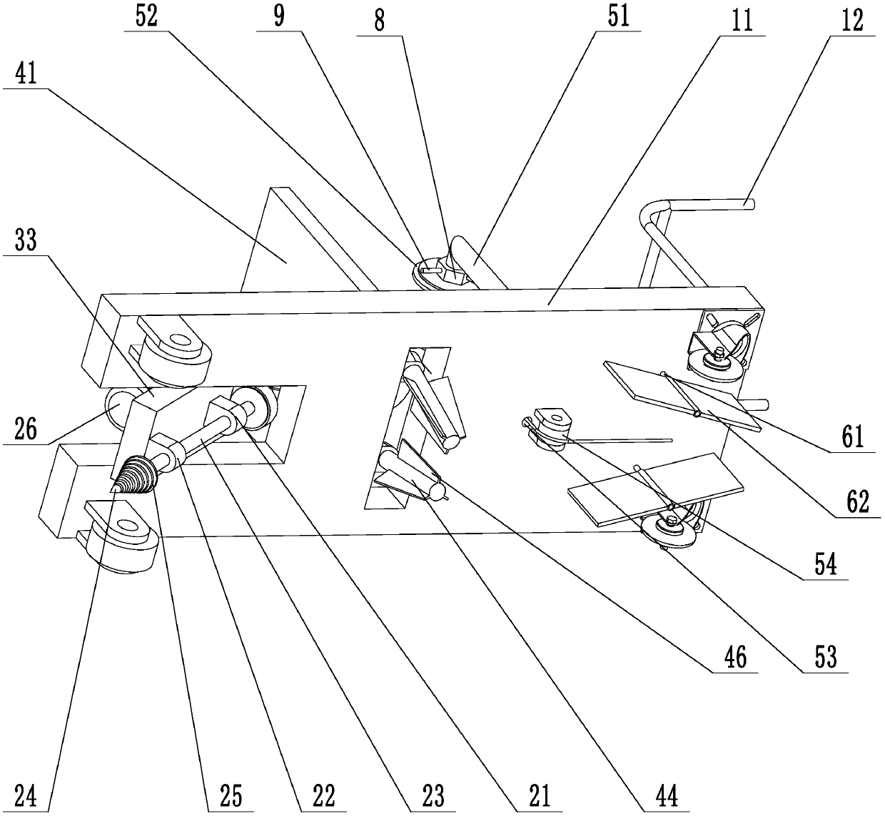
[0051] refer to figure 2 and image 3 , the long hole 31 is opened at the place near the front side of the mobile base 11 , and the rotating plate 33 is sleeved on the rotating shaft 32 and can rotate around the rotating shaft 32


PUM


Abstract

The invention relates to a cable laying device which comprises a movable base and a handrail arranged on the movable base, wherein a grooving mechanism, an expanding mechanism, a laying mechanism anda backfilling mechanism are arranged on the movable base; the grooving mechanism comprises a bearing support fixed to the bottom surface of the movable base, a rotating shaft in rotary connection withthe bearing support, a tip fixed to the front end of the rotating shaft, a groove arranged on the tip and a grooving power device arranged on the movable base; the expanding mechanism comprises a vertical plate perpendicularly fixed on the movable base, a vertical shaft in rotary connection with the vertical plate, a driving bevel gear arranged at the lower end of the vertical shaft, a lateral shaft in rotary connection with the vertical plate, a driven bevel gear arranged at the upper end of the lateral shaft, a stirring plate arranged at the lower end of the lateral shaft and an expanding power device arranged on the vertical plate. The cable laying device disclosed by the invention can be applied to on-site temporary cable laying and has the technological effects of convenient operation and quick laying speed.

Description


Claims


Application Information

Patent Timeline
Owner 河北盛伟电力工程有限公司
Why Eureka
Try Eureka