A refrigerant transmission sealing structure for superconducting motor

A technology of superconducting motors and sealing structures, which is applied in the direction of electromechanical devices, electrical components, electric components, etc., to achieve the effects of reduced assembly difficulty, easy structure, and increased dynamic pressure

Active Publication Date: 2020-08-04
WUHAN MARINE ELECTRIC PROPULSION RES INST CHINA SHIPBUILDING IND CORP NO 712 INST
View PDF3 Cites 0 Cited by
  • Summary
  • Abstract
  • Description
  • Claims
  • Application Information

AI Technical Summary

Benefits of technology

In this new design described in the current embodiment of the inventor's sealed system used in Super Conduction Motor Refrigeration Transmission Rotary Seals, there are several benefits compared to older designs such as improved fluid circulation or increased machine performance caused by enhanced lubricity between moving parts. However, these modifications have led to problems like excessive heat generation at certain points along the length of the pipelines where the fluids pass over them. Additionally, some versions of the original design had issues with maintaining tight tolerances when assembled together, which could lead to leaks if improperly installed. Overall, it suggests an improvement method called the zoom no-nozzle mechanism proposed earlier in the field.

Problems solved by technology

Technological Problem: Supercondensers (S) require better sealing properties due to their use within different types of systems such as liquid nitrogen or liquefied natural gases. Current methods involve using contact mechanisms like metal bellows or rubber rings which may lead to short circuits during operation. Therefore, new solutions aimed towards improving these components' ability to maintain tightness without causing excessive thermal stress would improve overall reliability while also being able to achieve efficient cooling capabilities.

Method used


Image

  • A refrigerant transmission sealing structure for superconducting motor
  • A refrigerant transmission sealing structure for superconducting motor
  • A refrigerant transmission sealing structure for superconducting motor

Examples


Embodiment Construction

[0021] The present invention will be described in further detail below in conjunction with the accompanying drawings.

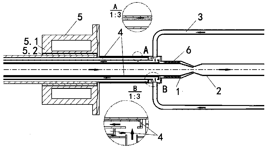
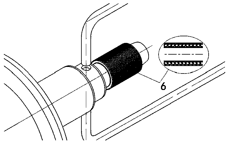
[0022] Such as figure 1 As shown, the refrigerant transmission sealing structure of the superconducting motor of the present invention includes a stationary intake pipe 1, a rotating intake pipe 2, a gas return pipe 3, a vacuum interlayer pipe 4, a magnetic fluid sealing device 5 and a labyrinth sealing structure 6. The magnetic fluid sealing The device 5 comprises a rotating part 5.1 and a stationary part 5.2. The refrigerant gas enters the rotating inlet pipe 2 from the cryogenic refrigerator through the static inlet pipe 1 and then passes into the superconducting motor to cool the superconducting magnet. After the gas is heated, it returns to the refrigerator through the return pipe 3 and other circuits for cooling. The return air temperature is higher than the intake air temperature. In order to avoid energy loss, the vacuum interlayer pipe 4 is used to ins


PUM


Abstract

The invention discloses a refrigerant transmission sealing structure of a superconducting motor, which comprises a stationary intake pipe, a rotating intake pipe and an air returning pipe. The stationary intake pipe and the rotating intake pipe are connected and a laval nozzle passage is formed at the joint. A vacuum sandwich tube is arranged between the stationary intake pipe and the air returning pipe, and the outer wall of the vacuum sandwich tube is provided with a magnetic fluid sealing device. Magnetic fluid is injected into the magnetic fluid sealing device. The joint of the stationaryintake pipe and the rotating intake pipe is provided with a labyrinth sealing structure for isolating the intake air and the return air. The structure of the invention can realize the goals of not toohigh machining precision and assembly difficulty reduction on the premise of ensuring no change in the refrigerant transmission rotatory sealing topological structure of the existing superconductingmotor and the internal leakage rate of the existing structure.

Description


Claims


Application Information

Patent Timeline
Owner WUHAN MARINE ELECTRIC PROPULSION RES INST CHINA SHIPBUILDING IND CORP NO 712 INST
Why Eureka
Try Eureka